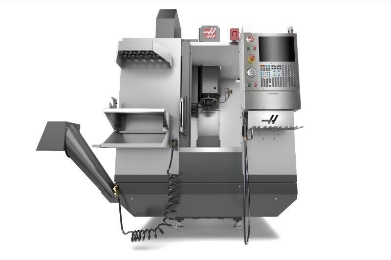
Industrial Insights: How to Spot Quality in Pre-Owned, Used, Secondhand, Surplus CNC Equipment Before Purchase HAAS DT-1 Drill & Tap Machining Center made in USA
Here is a deep “industrial-insights” guide and checklist for spotting quality (and hidden risks) when buying a pre-owned / used / surplus HAAS DT-1 Drill-Tap / Machining Center (made in USA). Use it as your on-site inspection playbook.
I’ll begin by summarizing key HAAS DT-1 specs (so you know the “good baseline”), then walk through what to check, how to test, warning signs, and how to interpret results.
Key specifications & features of the HAAS DT-1 (baseline for comparison)
Knowing the nominal spec of the machine helps you see when something is off. Here are the published specs for the DT-1:
- The DT-1 is a compact Drill/Tap/Mill center with full milling capability.
- Travels (X × Y × Z): 508 mm × 406 mm × 394 mm (20″ × 16″ × 15.5″)
- Spindle: BT-30, direct-drive inline, with up to 10,000 rpm standard; optional higher rpm spindles possible.
- Spindle motor power: ~15 hp (≈ 11.2 kW) in many configurations.
- Rapid traverse rate: up to 2,400 ipm (≈ 61 m/min) on X / Y / Z.
- Tool changer: 20 + 1 side-mount toolchanger (20 tool pockets plus one for the tool in the spindle)
- Max table load (evenly distributed): ~ 113 kg (≈ 250 lb)
- Coolant / chip handling: standard coolant tank, flood coolant, chip conveyor / removal as option.
- Air / utilities & electrical:
• Requires clean, dry compressed air for pneumatic / control circuits.
• Power: typically 220 VAC 3-phase or optionally 440 VAC via internal transformer (depending on configuration) - Machine physical layout / anchoring: the installation drawing indicates anchor spacing, clearances, etc.
These specs become your “reference target” — in inspection, you check whether the machine still meets or nearly meets these specs (or whether deviations indicate wear / damage / degradation).
Why extra scrutiny is needed for a used DT-1
Although the DT-1 is more compact and simpler than a full 5-axis center, there are still many possible failure modes. Some risk factors to be especially aware of:
- High-speed spindle stress: Because the DT-1 is designed for relatively high rpm (10,000 rpm or more in optional versions), the spindle bearings, rotor balance, and lubrication systems are under higher stress. Wear or imbalance shows more quickly.
- Precision required for holemaking / tapping: Since drilling and tapping are functions of this machine, repeatability, backlash, compensation for thread cycles, and tool rigidity are all more critical. Minor deviations can ruin threads or holes.
- Compact design / integration: Because the machine is compact, tolerances are tighter. There is less margin for “slop.” Wear in slideways, ball screws, or drive systems will show up more clearly in small machines.
- Control electronics, motion precision, tuning: High accelerations, fast rapids, and precise motion demand good servo tuning, minimal friction, healthy amplifiers, and good parameter stability.
So even though it’s “just a mill / drill / tap center,” you must treat it nearly as rigorously as a production machining center.
Pre-visit preparations
Before going on site, do the following to maximize what you can verify:
- Request documentation & history
• Service / repair logs, spindle rebuilds, tool change history, any crashes or incidents
• Machine hours (not just “powered-on,” but spindle usage, axis motion hours)
• Calibration / alignment checks, maintenance records
• Backups of control parameters, wiring diagrams, parts list, electrical schematics - Ask for a video / remote demonstration
• Jog X, Y, Z axes; run spindle through rpm range; cycle tool changer; run a sample tap / drill / mill job if possible
• Pay attention to noise, vibrations, chatter, delays, error codes - Pack or bring inspection tools
• Dial indicators, test bars, gauge blocks, edge finders
• Infrared thermometer or surface temperature probe
• Vibration sensor / stethoscope (if available)
• Known reference “coupon” or test part, if you can bring one - Bring or involve a specialist
• Someone fluent in CNC, servo systems, spindle dynamics, controls
• They can help interpret alarm logs, parameter settings, servo behavior - Check spare parts & support
• Are spindle bearings, drive amplifiers, control boards, decouplers, tool changer parts easily available in your region (or via your supply chain)?
• Are there local technicians familiar with HAAS machines - Know installation & transport constraints
• Machine weight, crane / rigging path, floor loading, anchoring, utilities, power, cooling
• Have expectation that the machine must be re-leveled and re-calibrated after transport - Prepare a scoring / inspection sheet
• List subsystems (spindle, axes, control, tool changer, geometry) with weightings so you can objectively score them on site
On-site inspection & rigorous test checklist for the DT-1
Below is a detailed, subsystem-by-subsystem checklist. Test across full travel, under different conditions (slow, rapid, loaded), and in both directions. Record as much quantitative data as possible.
| Subsystem / Area | What to Inspect / Test | What “Good / Acceptable” Looks Like | Warning Signs / Red Flags |
|---|---|---|---|
| Frame, base, castings | Visually inspect for cracks, weld repairs, distortions, uneven wear, misalignment | No cracks or structural repairs, no bending or sagging, uniform wear | Repair welds in structural zones, cracks, twisted frame, uneven base marks |
| Way covers / bellows / guards | Move axes (X / Y / Z) slowly in both directions; inspect covers for dragging, interference, sagging | Covers move freely, no contact / interference, no binding, no torn sections | Bellows torn, sagging covers, covers scraping table or column, debris trapped |
| Linear guideways / ball screws / backlash | Jog axis, reverse direction, check backlash with dial indicator, feel for roughness, dead zones | Minimal backlash per spec (few microns), smooth motion, no “sticky” zones | Excessive backlash, binding in certain ranges, “dead spots,” vibration or chatter in slow motion |
| Spindle & bearings | Run spindle from low → mid → high rpm, listen carefully for bearing noise, test runout with test bar, monitor temperature | Quiet across rpm, minimal vibration, runout within spec (µm level), stable temperatures | Grinding / knocking, humming noise, high vibration, high runout, spindle heat rise, unstable rpm |
| Tool changer / tool magazine | Cycle the tool changer, index all tool pockets, test tool retrieval / insertion, test for mis-index | Smooth, repeatable tool changes, no tool drops, consistent timing, no errors | Tool drop, misalignment, missed indexing, worn pockets, collision marks, failed cycles |
| Axes drives / servo performance | Perform full rapid moves, direction reversals, acceleration/deceleration, load/unload cycles; check for servo fault alarms | Stable axes motion, no alarms, axes reach full speed / travel, good responsiveness | Servo trips, overshoot / undershoot, axis faults, vibration, instability, heating of drives |
| CNC control & electronics cabinet | Open cabinet, inspect wiring, look for burnt components, cleanliness, dust, check fans; power up, check alarm logs, I/O status, parameter integrity | Neat wiring, no burnt wires or connectors, fans working, control boots cleanly, parameter memory stable, no persistent alarms | Burnt contacts, broken wires, fan failure, control boot errors, missing modules, noisy / flickering screens |
| Coolant / lubrication systems | Examine coolant tank (cleanliness, rust, sludge), pumps, filters, piping; check that auto-lubrication (if present) works | Clean coolant, pumps operate, no leaks, filters not clogged, lubrication system functional | Dirty / contaminated coolant, leaks, pump failures, lubrication starvation, clogging, rust in coolant tank |
| Chip handling / conveyors / removal | If present, test chip conveyor or removal, inspect for jam, smooth operation | Chips evacuated cleanly, conveyor runs reliably, no blockages | Jammed conveyor, chips backed up, motor failures, broken or misaligned conveyor paths |
| Thermal stability / drift | Run machine for some time (warm-up), then re-measure key geometry or run test cuts to detect drift | After warm-up, machine stabilizes; geometry / measurements remain steady | Drift over time, part sizes changing, dimension shift mid-cut, inconsistent results |
| Accuracy / repeatability tests | Use gauge blocks, test bars, reference parts, perform multiple cycles of movements and measure | Good repeatability (within expected tolerances, e.g. a few microns), consistency across range | Variation in repeated runs, deviation across travel, out-of-spec geometries, inconsistent reading |
| Full-load / cutting test | If allowed, mount a typical workpiece and run a real drilling / tapping / milling cycle; watch for chatter, stability, finish, alarms | Smooth operation, stable feed, good finish, no alarms or instability under load | Chatter, tool breakage, alarms under load, poor finish, inconsistent performance, lost steps |
| Software / control features & options | Check that tapping cycles / rigid tapping / macro cycles / probing / high-speed features work, check offsets, check backup restores | All features functional, no disabled modules, parameters intact, stable behavior | Missing or disabled features, control crashes, failure of tapping or macro cycles, lost parameter memory |
| Documentation & spare parts | Confirm presence of operator manual, maintenance guide, parts catalog, wiring diagrams, parameter backups | Full documentation, spare parts list, parameter backup stored externally | Missing or incomplete manuals, no foreign parts list, undocumented modifications, no backups |
How to interpret what you find & decision logic
After you’ve run through the tests, here’s how to interpret results and decide whether to proceed, negotiate, or walk away:
- Cosmetic vs. functional defects
• Cosmetic issues (paint wear, minor dents, surface scratches) are acceptable within reason.
• But functional problems—spindle degradation, high backlash, control instability, geometry errors—are serious. - Estimate repair cost, downtime & risk
• For any identified defect, get a quote for parts & repair, and estimate associated downtime and risk.
• Use those costs to reduce your offer or demand repair before sale. - Spare parts / support availability
• The value of the machine depends heavily on whether you can easily source parts (spindle bearings, drive amps, tool changer modules, control boards) in your region.
• If spare parts are hard to get, even a “good” machine becomes a liability. - Remaining useful life
• Consider how much “useable life” remains, based on hours, wear, or repairs you’ll need soon.
• If many subsystems are nearing end-of-life, that risk must be factored in. - Control / software obsolescence
• Even if mechanical systems are in good shape, an outdated or unsupported control is a big risk.
• Ensure the HAAS control (firmware, modules, memory, interfaces) is healthy and that you can load your programs or interface with your CAM system. - Negotiation & acceptance window
• Negotiate an “acceptance / testing window” (e.g. 30 or 90 days) after delivery, during which you can test the machine under real production conditions and reject or demand fixes if performance is off. - Transport & reinstallation risk
• Expect that moving the machine will shift alignment. Always budget time (and cost) for re-leveling, calibration, geometry checks after installation. - Weighted evaluation / decision threshold
• Assign more weight to critical subsystems (spindle health, axis precision, control electronics, tool changer).
• If the machine fails or scores poorly in a high-weight area, that alone may justify rejection, even if most other areas are fine.