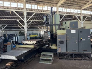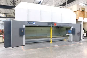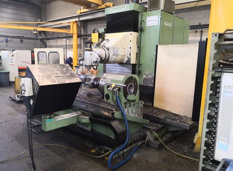
Industrial Insights: How to Spot Quality in Pre-Owned, Used, Secondhand, Surplus CNC Equipment Before Purchase Anayak HVM 3300 CNC Bed Type Milling Machine made in Spain
Here’s a deep-dive “industrial insight” guide for evaluating a pre-owned / surplus Anayak HVM 3300 (bed / travelling-column / bed-type milling machine) before purchase. I’ll include known spec benchmarks, critical inspection points, functional tests, red flags, and negotiation safeguards.
1. Baseline / Nominal Specifications (What to Expect)
Before you inspect, you should know what the “factory” or typical spec is (so you can detect deviations). Based on listings and catalog data, here are common specs for the Anayak HVM 3300:
| Parameter | Typical / Published Value |
|---|---|
| Table / Work Surface | ~ 3,300 mm × 1,000 mm |
| Axes Travel | X: ~ 2,700 mm Y: ~ 1,000–1,200 mm Z: ~ 1,000 mm (some listings) |
| Spindle / Head | ISO 50 taper / DIN 69871 standard tool mounting Speed range ~ 20–4,000 rpm Spindle motor power: ~ 30 kW (in many adverts) |
| Tool Changer / Head Indexing | 40-position tool changer in many units Automatic multi-angular / indexing milling head (~2.5° increments in both head axes) |
| Feed / Rapid Rates | Feed all axes ~2 to 10,000 mm/min, rapid ~10,000 mm/min in many adverts |
| Maximum Table Load | Some adverts list ~5,000 kg (5 tons) capacity |
These are your “comparison yardsticks.” If the machine you inspect falls short significantly in any of these areas, that’s your red flag.
2. Pre-Visit Document / Context Gathering
Before going onsite, ask the seller to provide:
- Maintenance & service logs (lubrication, guideway regrinds, spindle overhauls)
- Operating hours (total vs cutting hours)
- History of repairs, part replacements (spindle bearings, guideways, head indexing mechanism, tool changer)
- Original manuals, wiring diagrams, part lists, electrical / hydraulic / pneumatic schematics
- CNC / control system version, software licenses
- Any past alignment / calibration reports
- Retrofitting / modification history (if someone has modified or upgraded components)
Having this documented history lets you cross-check claims and helps you know where to focus more scrutiny.
3. Visual & Physical Inspection On-Site
Once you’re in front of the machine, you need a methodical walkaround and hands-on inspection. Use measuring tools (dial gauges, straightedges, feeler gauges) if possible.
3.1 Structure, Base & Frame
- Check the bed, columns, guide surfaces for cracks, weld repairs, distortions, or evidence of rework.
- Look for signs of corrosion, pitting, abrasion, especially on exposed surfaces.
- Inspect access covers, doors, guards — missing or poorly fitting covers often indicate neglect.
- Check how the machine is mounted: is the foundation solid? Are there signs of shifting or settling?
- Verify that the machine frame is square and without twist, especially if the columns or base have been altered.
3.2 Guideways, Slides & Linear Motion
- Inspect linear guide rails / bed ways / slides for wear, scoring, chipped edges, pitting, or discoloration.
- Manually (if possible) move axes slowly and feel for stick-slip, binding, or uneven friction.
- Check wipers, scrapers, seals along ways — if these are failing, debris ingress may have damaged motion surfaces.
- Inspect ball screws / lead screws / nut assemblies (if in use) for thread wear, backlash, and smooth engagement.
- Examine encoder scales, linear scales, feedback readers — look for damaged scale surfaces or dirt deposits.
3.3 Spindle, Head & Milling Mechanism
- Inspect the spindle nose / taper for wear, scratches, or burrs.
- Using a test bar (if you have the equipment), check spindle runout (radial & axial).
- Rotate the spindle manually (if possible) and listen/feel for bearing noise or roughness.
- Check the spindle lubrication / coolant / oil lines for leakage, blockages, or signs of repairs.
- Inspect the automatic indexing head / angle head mechanism: check for smooth indexing motion, backlash, play, and condition of gears.
3.4 Tool Changer & Tool System
- Operate the tool changer (if possible) — observe whether picks, placement, magazine indexing are clean and precise.
- Inspect tool pockets, clamping surfaces, and wear at interfaces.
- Check that tool change motions (arm movement, magazine rotation) are smooth without collision.
- Examine the tool clamping actuator (hydraulic / pneumatic / mechanical) for leaks or play.
3.5 Table / Work Holding & Load Handling
- Inspect the table surface (T-slots, flatness, wear) for dents, gouges, repairs.
- Check table mounting and rails (if it moves) for alignment and play.
- Verify maximum load capacity claims: see if the structure shows signs of being overloaded historically (deformations, bending).
- Inspect clamping systems, fixtures, supports and their condition.
3.6 Auxiliary Systems (Coolant, Chip Handling, Drives)
- Inspect coolant system, pumps, piping, filters, chiller if present — ensure no leaks, blockages, or rust.
- Check chip conveyor, tramp oil separators, filtration units for wear or damage.
- Verify power feed drives, motors, couplings, belts, gearboxes for soundness, alignment, and absence of play.
- Inspect electrical cabinet: dust, moisture, burnt wires, modifications, neatness of wiring, grounding.
- Check control panel, operator interface, HMI, pendant — all buttons, switches, emergency stop, displays should work reliably.
4. Functional & Performance Testing
Only through actual operation will hidden defects show themselves. Here’s how to stress-test the machine:
4.1 Dry / No-Load Motion Test
- Jog each axis (X, Y, Z) through full travel at slow, medium, and fast speeds. Listen & feel for stuttering, binding, or irregular motion.
- Reverse directions, sudden stops/starts to see how smoothly the motion control handles inertia.
- In interpolated motion (e.g. move diagonally in XY, or move Z while X moves) observe smoothness and whether axes stay synchronized.
4.2 Tool Change & Indexing Test
- Execute several back-to-back tool change cycles — watch for mispicks, hesitation, collision, or alignment errors.
- Test the indexing of head / angle head (if applicable) through its full angular range.
- Watch how precisely the head returns to original orientation (repeatability).
4.3 Simulated Machining / G-Code Test
- Run a simple test program (contours, pockets, circles) without heavy cutting to see how the axes track.
- Pause, reverse, command small incremental moves — verify motion fidelity and responsiveness.
- Observe acceleration/deceleration behavior and jerk control.
4.4 Actual Machining / Test Cuts
- Perform cuts on a representative material (steel, aluminum, etc.) with moderate cut parameters.
- Produce known geometries (e.g. pocket, hole, slot) and measure the output with precision instruments (CMM, micrometers).
- Check dimensional accuracy, straightness, surface finish, and taper.
- Observe any chatter, vibration, or tool deflection effects.
- If possible, run the machine under different load conditions (light and moderate) to see how it behaves.
4.5 Long-Run & Thermal Stability Test
- Run a sustained machining cycle (or at least several hours of continuous operation) to see how the machine behaves under thermal stress.
- Monitor for drift, thermal expansion effects, backlash creeping, or control deviations.
- Listen and feel for any bearing heating, degradation, or changes in noise.
4.6 Repeatability & Backlash Tests
- Use a dial indicator (or displacement measurement tool) to command back-and-forth moves (e.g. +10 mm, –10 mm, +10 mm) and check how precisely the machine returns.
- Do this in multiple directions and axes.
- Test for settling error or “creep” in motion when stationary load is removed.
5. Red Flags & Deal-Breakers
Here are warning signs that may indicate a machine is too risky or will require heavy refurbishment:
- Deep wear, scoring, pitting, or gouges on ways, guide rails, slides
- Spindle runout beyond acceptable tolerance (especially if bearings are degraded)
- Backlash or play in head indexing, tool changer, or axes
- Tool changer mispicks, collisions, or mechanical hesitation
- Serious corrosion or water damage in coolant systems, cabinets, or mechanical structures
- Overt modifications / “hacks” (wiring splices, makeshift brackets, nonstandard parts)
- Missing or nonfunctional accessories (guards, covers, supports)
- Electrical cabinet damage (burn marks, overheating, poor wiring)
- Control system obsolete or license-unavailable
- Lack of maintenance records or history
- Inconsistent or failed test cuts / motion during your testing
- Unavailable or rare parts for key subsystems (spindle bearings, head indexing gears)
If you find multiple red flags, your risk of unexpected costs is very high.
6. Economic & Lifecycle Assessment
- Estimate remaining life of major wear components (spindle bearings, guideways, tool changer parts, indexing mechanism).
- Check availability, cost, and lead time for spares (especially for head indexing, spindle components, tool changer arms).
- Compare the asking price plus expected refurbishment costs vs price of a refurbished or new machine of equivalent size.
- Factor in transport, installation, leveling, alignment, calibration, commissioning.
- Secure a performance acceptance clause or warranty (if possible) for the first few months.