28/10/2025
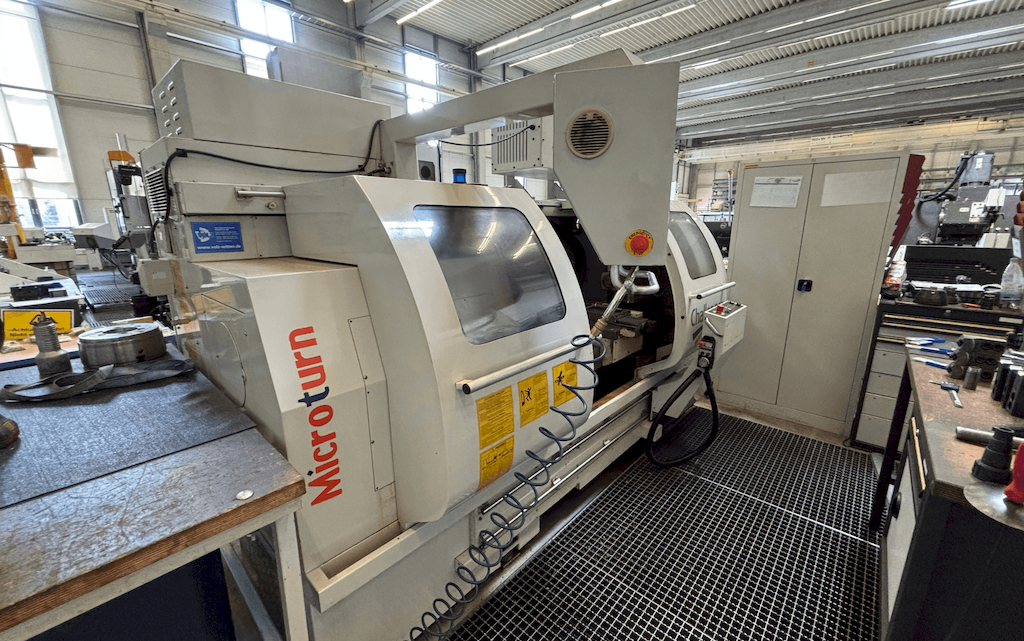
From Inspection to Installation: What to Verify Before Buying a Pre-Owned, Used, Secondhand, Surplus MICROTURN Challenger BNC 1840 CNC Cycle Controled 1 Meters made in Taiwan
Below is a detailed checklist—from inspection through to installation—tailored for a used or surplus MICROCUT Challenger BNC‑1840 (cycle-controlled CNC lathe) made in Taiwan (or via Taiwan OEM). Some specs are drawn from known listings to help you benchmark what to verify.
1. Pre-Purchase / Inspection Stage
A) Documentation & Machine Identity
- Check the machine model and serial number plate: model “BNC-1840”, confirm year of manufacture. For example one listing shows year 2004.
- Verify that the OEM is indeed MICROCUT (Taiwan) and that the listing or seller has not mis-labelled it (some listings show “Country of Origin: Taiwan”).
- Ask for maintenance records, hours of operation (if available), previous usage profile (batch production, single-piece runs, etc).
- Confirm control unit type (e.g., FAGOR 8055/8055FL in many listings).
- Check if tooling, chucks, workholding, bar feeders or other accessories are included; if not, get list and condition.
B) Visual & Mechanical Condition
- Check bed ways, cross-slide, longitudinal travel for wear: look for excessive play, scoring, pitting.
- Inspect spindle: bore size, taper (one spec shows Ø65 mm bore).
- Check chuck(es) and jaws: condition, run-out, mounting flange, integrity.
- Examine tool turret or tool-change mechanism: condition of tool posts, quick-change toolpost, holders, tool-change reproducibility. Listings show quick-change toolpost.
- Inspect turrets, live tooling (if equipped), bar-feeder spindles, tailstock (if applicable) for condition.
- Check coolant / filtration / chip conveyor / lubrication systems: condition of pumps, filters, hoses, visible contamination or neglect.
- Examine the gearbox or spindle speed drive system (if multi-step gearbox or automatic spindle speed changer). For example older spec shows a “2-step automatic transmission gear box” for BNC-1800 series.
- Check electrical cabinet: wiring condition, cleanliness, fan/filtered ventilation, signs of overheating, water ingress, modification history.
- Check control panel, screen, keypad, axis drives: signs of replacement, retrofits, firmware version.
- Run machine (if possible) through zero-movement tests: move axes, listen for unusual noises, check for vibration, backlash, spindle run-out.
- Measure spindle run-out with test bar, chuck + dial gauge to verify within usable tolerance — important for precision turning.
- Check alignment: bed to tailstock, turret to spindle centreline, headstock alignment etc.
C) Specification Verification
- Confirm key specs match what you need: e.g., swing over bed (475 mm in some listings)
- Distance between centres/turning length: e.g., 1000 mm in many listings.
- Spindle speed range: e.g., 100-4500 rpm in listing.
- Spindle bore, swing over cross slide, machine footprint, weight: verify these to ensure your factory space / base can handle.
- Confirm power requirements: voltage, phases, KVA requirement (some listing: 415 V, 20 KVA).
- Confirm that the machine’s travel (X/Z or X/Y depending configuration) meets your part dimensions.
D) Condition Report & Risk Assessment
- Ask for recent position/operating hours log, or at least an approximate usage.
- Determine wear parts that might need immediate replacement: spindle bearings, hydraulic seals, turrets, drive belts, cooling system.
- Ask whether the machine has been in continuous production, or idle for long time — idle machines may have different risks (rust, condensation, deterioration).
- If machine is overseas: check shipping risks, dismantling, re-installation capability, spares availability for older controls or components.
- Check availability of manuals, parts lists, software backups, control units spare parts.
- If machine modified or retrofitted: get history and documentation.
2. Purchase & Logistics Stage
- Agree on inspection access, possibly bring independent technical auditor to validate condition.
- Secure transport logistics: due to machine weight, size (example listing weight ~3000 kg, footprint 3000×1850×2000 mm).
- Determine base/foundation requirements at your site: does machine need concrete pad, bolting, level base, isolation, vibration dampeners?
- Plan for utilities: power supply (phase/voltage/frequency), air supply, coolant, chip disposal, hydraulic/lubrication fluids.
- Plan for rigging/unloading: crane capacity, forklift access, access doors, lifting lugs on machine.
- Agree on terms of transport, risk, insurance during transit, export/import (if international).
- Schedule delivery date, installation timeline, coordinate removal of old machine if workspace needs clearing.
3. Installation & Commissioning Stage
A) Site Preparation
- Verify floor structure can support machine weight plus dynamic loading, shipping weight plus foundation.
- Level concrete base, ideally poured pad with anchor bolts.
- Provide proper ventilation, lighting, chip disposal/tray systems.
- Install power: correct voltage, phase, frequency, surge protection, isolation transformer if required, UPS for control.
- Provide air supply of correct pressure, clean dry air for pneumatics (if machine has pneumatic elements).
- Ensure coolant and coolant-filtration systems are installed, and chip conveyor/tray ready.
- Set up necessary safety protections: guards, chip shields, emergency stops, door interlocks, ventilation of fumes (if any).
B) Mechanical Installation
- Move machine into position, set anchor bolts, take initial rough level.
- Use precision level / electronic level to fine-level bed to manufacturer spec.
- Once levelled, torque anchor bolts per spec, fill base with grout if needed (some machines require).
- Connect utilities (power, air, coolant, hydraulics).
- Remove shipping bolts/locks, ensure spindle is freed per OEM instructions.
- Fill lubrication systems, replace fluids if necessary (especially if machine was idle, stored).
- Connect chip conveyor and ensure it is correctly oriented and functioning.
- Verify emergency stop, guarding, interlocks.
C) Electrical / Control Setup
- Turn on control and drives. Check for fault codes, faults history.
- Load machine control software backups, if available, and verify control configuration (FAGOR or other).
- Set zero offsets, tool offsets, spindle offsets as required.
- Check axis servo drives: set gains, test movement at slow speed first.
- Check spindle drive, speed range, direction, air blast/spindle help systems.
- Check turret/tool changer: operation, indexing, repeatability, tool-holder run-out.
- Run through dry cycle (without workpiece) to verify axis travel, homing, limit switches, soft stops.
- Set up coolant pump, coolant through tool if applicable, chip conveyor/run-out.
D) Trial Run & Alignment Verification
- Mount test piece (preferably known part) and perform turning operation. Monitor:
- Part accuracy (diameter, length)
- Surface finish quality
- Spindle run-out, chatter/vibration
- Tool change reliability
- Use dial gauges and test bars to check spindle run-out and turret repeatability.
- Measure actual machine alignment: bed straightness, tailstock alignment (if applicable), cross-slide squareness.
- Monitor machine during initial production for vibration, noise, temperature increases (bearings, drives, temp of electrical cabinet).
- Monitor chip evacuation and coolant return.
E) Final Equipment Commissioning
- Set up maintenance schedule: lubrication intervals, filtration checks, spindle coolant, hydraulic oil conditions.
- Ensure spare parts list is documented: especially wear items for this specific model.
- Train operators on machine-specific controls, safety, tooling changes, emergency procedures.
- Create documentation: serial numbers, machine history, service logs, installation record.
- Define Key Performance Indicators (KPIs) for machine: cycle time, scrap rate, accuracy hold‐down, tool change time.
4. Specific “Red Flags” for This Model
- Because this machine appears to be older (early 2000s) you should watch for:
- Control obsolescence (FAGOR 8055/8055FL) — check if spare parts/software updates still available.
- Turret/tool-changer wear — repeated indexing can cause accuracy drop.
- Spindle bearings: high cost to replace; ask about run-hours, noise, heat.
- Bed wear: look for signs of heavy hard turning or many hours on heavy duty.
- Chip evacuation: older machines may have less efficient chip conveyor systems.
- Electrical wiring: older machines sometimes have upgrades by previous owners; ensure wiring and components meet your country’s safety standards.
- Shipping/installation risk: large footprint and weight (approx 3000 kg for some listing of this model)
5. Summary & Next Steps
- Use the above checklist to perform a pre-inspection (on-site or via video/live stream).
- Get a written condition report, listing any parts requiring replacement.
- Negotiate price including any required repair/refurbishment or spare parts cost.
- Plan logistics and site preparation well before machine arrival.
- Upon arrival, perform mechanical & electrical installation steps and run trial production before full production.
- Maintain records and plan for preventive maintenance to maximise lifespan.