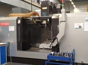
From Factory Floor to Your Workshop: Evaluating a Pre-Owned , Used , Secondhand, Surplus CNC Machines Before Purchase Toyoda / Awea BM-1600 CNC Vertical Machining Center made in Japan
Below is a detailed, machine-type–adapted checklist and evaluation guide for a pre-owned / used / surplus Toyoda / AWEA BM-1600 (vertical machining center, likely Japanese or Taiwanese origin, often sold under “Toyoda / Awea” branding). Use this to vet its condition, hidden risks, and refurbishment costs before you commit.
0. Background & Typical Benchmark Specs (for BM-1600 / BM Series)
Before you even go to see the machine, get as much of the original spec sheet, brochures, manuals, or factory documentation as you can. Use these as your “target envelope” against which you compare what you observe. Below are typical published data for the BM-series (BM / BM-MAX), especially BM-1600, which is referenced in multiple sources.
| Parameter | Typical / Published Value | Notes & Sources |
|---|---|---|
| X / Y / Z travels | X = 1,600 mm, Y = 800 mm, Z = 800 mm | BM-MAX spec sheet: BM-1600 MAX has X=1,600 / Y=1,000 / Z=800 in that series. In used spec sheet: 1600 / 800 / 800 for BM-1600 bought used. |
| Table size / load | Table size Y direction ~800 mm, load ~2,000 kg | Exapro listing: table width 800 mm, max part weight 2,000 kg. BM-MAX spec: table load 2,000 kg for BM-1600 MAX. |
| Spindle speed / taper / motor | Max 6,000 rpm, taper BT-50 typical, 15 / 18.5 kW or similar | Used spec sheet: spindle 6,000 rpm, spindle motor 15 / 18 kW. BM-MAX spec: BT50, 15 / 18.5 kW, 6,000 rpm. |
| Tool magazine / ATC | 24-station tool changer | BM-MAX spec: tool magazine 24 T. Used spec sheet also lists 30 as optional / variant. |
| Rapid traverse / feed rates | X/Y rapid ~20 m/min, Z ~18 m/min | BM-MAX spec: X/Y 20 m/min, Z 18 m/min. Used spec sheet: same values 20 / 20 / 18. |
| Machine weight / size | On the order of ~13,000 to 15,000+ kg | BM-MAX spec lists machine weight (for BM-1600) around the 13,000 kg region. |
| Control / axis | Typically 3 axes; with Fanuc 0i-MF or comparable control | Used spec sheet mentions control = FANUC 0i-MD / 0i-MF variants. BM-MAX spec mentions “Control system FANUC Oi-MF Plus.” |
These numbers help you detect deviations: for example, if you find only 12 tool stations, or rapid feeds much lower than 20 m/min, that’s an indicator of wear, modification, or downgrade.
Also, note that many “Toyoda / Awea” machines are actually built by AWEA (a Taiwanese company) under licensing or co-branding — the “Toyoda / Awea” label often indicates a regional or OEM branding relationship. The specs above are drawn from AWEA’s BM family.
1. Pre-Inspection / Remote Requests & Questions
Before your on-site visit, try to gather the following:
| Item | What to Ask / Request | Why It’s Important |
|---|---|---|
| Maintenance / service records | Dates of spindle rebuilds, guideway refurbishment, key repairs | A history of maintenance shows how well the machine was cared for |
| Hours / usage | Total machine hours, cutting hours, utilization rate | Swiss or vertical machines degrade with heavy usage |
| Crash / incident history | Any spindle collisions, overtravel strikes, tool crashes | Structural damage or hidden misalignment may result |
| Retrofits / control changes | Control replaced, axis expanded, spindle changed, ATC upgrades | Such modifications affect parts, compatibility, reliability |
| Spare parts / tooling inventory | Do they have extra tool holders, spares, motors, drives | Missing spares often lead to extended downtime |
| Electrical / utility specs | Voltage, phases, coolant system, power draw, hydraulic systems | Ensure your facility can support the machine |
| Rigging / transport plan | How they intend to disassemble, lift, move, reassemble, align | Missteps here can badly damage the machine |
| Inspection rights / trial | Ability to power up, jog axes, run test cuts, sample job | Without real tests, hidden wear may be missed |
| Warranty / acceptance clause | Can you reject the machine later if hidden faults appear? | Provides risk protection |
If the seller resists providing this information, that is a red flag.
2. Visual / Structural & Static Inspection (Before Power)
When you arrive, before energizing anything, walk all around the machine with this checklist:
A. Structure & Castings
- Inspect the machine base, column, cross-beam, saddle, table supports for cracks, weld repairs, distortions, or signs of misalignment.
- Check for uneven paint wear, corrosion, pitting, particularly on surfaces near coolant or chip flow zones.
- Observe way covers, bellows, telescopic guards — any damage, torn covers, or missing sections indicate chip/coolant penetration which accelerates wear.
- Examine panels, doors, SMT cabinet covers, electrical enclosures — missing or deformed covers are a sign of rough handling or neglect.
- Check for wiring harness, cable carriers, conduit — look for abrasion, exposed wires, patched cables, or non-standard repairs.
- Inspect coolant / lubricant piping, ducts, reservoirs for leaks, corrosion, rubber hose aging, or misfits.
- Examine the tool magazine / ATC arm structure — bent arms, missing fingers, wear or scarring are red flags.
- Inspect the spindle nose area, tool-change interface, and the column-spindle intersection for damage.
B. Static Mechanical Checks (No Power)
- Move axes manually (if possible, or via slow jog under power with careful control) to feel for binding, rough spots.
- Use feeler gauges or small indicators to check for play / backlash in slides / axes — push in one direction, reverse, see how much “dead” movement occurs.
- Mount a dummy tool / test arbor (if accessible) and gently test for axial / radial play (wiggle) in the spindle / tool interface.
- Other mechanical pivot joints, linkages, or sliding parts: check for smooth motion, looseness, or binding.
- Inspect lubrication ports, grease fittings, oil lines: check for blockages, missing fittings, or oil leakage.
- Check alignment of the table, slideways visually with a straightedge or level if possible.
Any sign of structural damage, severe play, or misalignment is cause for deep discounting or cautious consideration.
3. Power-Up & Basic Electrical / Control / Drive Tests
Once the static inspection is acceptable, you can power up (with appropriate safety precautions, interlocks, grounding). Proceed with these basic tests:
- Observe boot / startup of the CNC control: check for errors, missing modules, warnings, or fault messages.
- Test the control panel, buttons, switches, hand wheel, display, emergency stop — everything should respond properly.
- Switch to manual / jog mode and move each axis slowly. Check for smooth motion, absence of drive fault alarms, stutters or jerks.
- Test limit switches, homing, zeroing functions — axes should detect home/limit positions correctly.
- Monitor the motor / drive currents (if possible) when moving — any surges or anomalies can hint at drive or motor issues.
- Check the spindle control: startup / stop, forward / reverse if available.
- Test override functions (feed override, rapid override) to verify control responsiveness and correctness.
If the control or axes refuse to initialize cleanly, or drives fault even under light loads, that suggests deeper electrical or servo system problems.
4. Motion Tests, Accuracy & Repeatability Checks
Assuming basic power-up is good, stress-test the axes and control to discover hidden problems.
A. Axis Motion & Reversal Tests
- Command each axis to move at different speeds (slow → medium → faster) and observe whether motion is smooth, linear, without vibration or jerk.
- Reverse directions and measure backlash / reversal error for each axis using a dial indicator or precision instrument.
- Repeated approach to the same point from different directions and see how closely the axis returns (repeatability test).
- Execute combined axis moves (e.g. linear interpolation or circular paths) if the control supports it — check for coordination, synchronization errors, or non-uniform motion.
- If available, do a ballbar test or circularity test to detect geometric or servo tuning errors.
B. Spindle / Tool Interface Tests
- Run the spindle at multiple speeds and listen for bearing noise, hum, vibration.
- Mount a test indicator on the spindle or a tool and measure radial runout (wear, taper damage, interface error).
- Let the spindle run under no-load for extended time and observe for drift in vibration or noise.
- If possible, perform a light machining cut (milling, face) and observe spindle steadiness, chatter, or deviation under load.
C. Sample Machining / Test Part
- Insist on performing a test part (or sample cut) with material suitable to the machine’s expected use. For example, face mill, pocket, slot, ramp, etc.
- Measure the outputs: dimensional accuracy, flatness, surface finish, repeatability, geometric consistency.
- Try corners of the working envelope (near limits) to stress the machine’s full range.
- Observe chip evacuation, coolant flow, and cleanliness in the machining area.
- After cutting, check the workpiece for deviations and compare to tolerance.
If the machine cannot hold tolerances or produces inconsistent results in test machining, that is a serious red flag.
5. Geometric / Alignment / Metrology Validation
Bringing metrology tools (straightedge, indicators, gauge blocks, laser systems) or a metrology technician allows you to validate its geometric integrity.
- Check straightness of axes (X, Y, Z) across full travel to detect bow, sag, or deflection.
- Check parallelism of key axes (table surface vs spindle axis, X vs Y).
- Verify orthogonality / squareness between axes (X vs Z, Y vs Z).
- Command known distances and measure actual vs intended — detect scale error, linearity deviation.
- After warm-up (run for some time), recheck alignment to detect thermal drift.
- At extremes of travel, verify that geometry holds and that deflection or twist is not present.
- Check alignment of tool changer, spindle to table, and interface between head / column.
Some geometric deviations can be compensated or shimmed, but structural distortion or excessive wear is costly or impossible to fully remedy.
6. Estimating Refurbishment / Repair Costs & Risk Buffer
Even a well-kept used BM-1600 will likely need work. Prepare a realistic budget. Common items include:
- Spindle bearing replacement or rebuild
- Repairing or regrinding worn way surfaces / guideways
- Ball screw / nut refurbishment or replacement
- Servo drive / motor repair or replacement
- Control electronics repairs, I/O boards, wiring harness refurbishment
- Alignment, calibration, shimming, compensation adjustments
- Repair or rebuilding of tool changer (fingers, index mechanism)
- Replacement of sensors, limit switches, encoders
- Lubrication / coolant / filtration system overhaul
- Replacement of covers, way wipers, seals, gaskets
- Transport, rigging, leveling, installation, commissioning
- Spare parts package (bearings, seals, fasteners)
- Contingency (15–25 %) buffer for unforeseen defects
Because a milling center’s accuracy is highly sensitive to alignment, small wear or misalignments can degrade performance significantly — anticipate that fine-tuning efforts will be required.
7. Red Flags / Deal Killer Conditions
While inspecting and testing, some findings should raise serious alarms. These may justify steep negotiation discount or walking away.
- Spindle with audible noise, vibration or heating problems indicating worn bearings
- Control / CNC that fails to boot cleanly or shows persistent servo / I/O errors
- Excessive backlash or slop in axes that seems uncorrectable
- Structural damage: cracks, weld repairs, distortions in column, bed, cross-beam
- Misalignment so large that machining errors are obvious in test cuts
- Tool changer / ATC that fails to index, has bent arms, missing fingers
- Missing or severely damaged way covers or protective shields (letting chips / coolant penetrate)
- Obsolete or unsupported electronic modules or drives with no spares
- Machine cannot produce acceptable test part under load
- Non-linear behavior or large deviations near travel limits
- Excessive thermal drift, inability to maintain geometry over time
- Seller refusing testing or trial cuts, or unwilling to provide documentation / warranty
If you see multiple red flags, the risk and potential repair cost may outweigh the purchase.