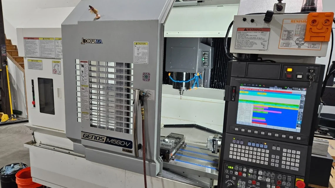
From Factory Floor to Your Workshop: Evaluating a Pre-Owned , Used , Secondhand, Surplus CNC Machines Before Purchase Okuma Genos M560-V CNC Vertical Machining Center 4-Axis made in Japan
Here’s a detailed, structured evaluation guide (with specs & best practices) for assessing a pre-owned / used / surplus Okuma Genos M560-V (4-axis or potentially 5-axis variant) vertical machining center before purchase. Use this as a “due diligence” roadmap from factory floor to your workshop.
I. Know the Machine — Baselines & Specification Check
Before visiting, acquire the original documentation (brochure, service manuals, factory data). These are your “reference envelope” — any large deviation is a red flag.
Here are some published specs for the Okuma Genos M560-V series to use as benchmarks:
| Parameter | Published Value | Notes / Source |
|---|---|---|
| X / Y / Z travels | X = 1,050 mm, Y = 560 mm, Z = 460 mm | The “Affordable Excellence” product page gives X×Y×Z = 1,050 × 560 × 460 mm. |
| Table size | 1,300 mm × 560 mm | Okuma Europe site lists table size 1,300 × 560 mm. |
| Spindle speed (max) | 15,000 rpm | The product page states spindle speed up to 15,000 rpm. |
| Spindle motor power | 22 / 18.5 kW | Okuma Europe cites motor kW = 22 / 18.5. |
| Tool magazine / ATC | 32 tools | The product page notes a 32-tool magazine. |
| Rapid traverse (X/Y) | ~ 40 m/min | From the product page (X–Y rapid) = 40 m/min. |
| Rapid traverse (Z) | ~ 32 m/min | The Z rapid is given as 32 m/min. |
| Taper / tool interface | #40 taper (CAT-40 / BT-40) | MachineTools.com listing shows taper #40. |
| Machine weight / footprint | MachineTools.com lists ~16,500 lbs (~7,485 kg) for a used unit | For the Genos M560-V, Machinetools data gives weight 16,500 lbs. |
Because the Genos M560-V is relatively modern, it is likely in better shape than many older machines — but wear, misuse, and deferred maintenance can take a toll.
Use these numbers to compare what the seller claims. If the inspected machine falls far short (in travel, spindle rpm, tool count, or rapid feed), that’s a warning sign of wear or modification.
II. Pre-Inspection / Offsite Questions & Required Documentation
Before going to see the machine, gather or ask for:
- Maintenance / Service Logs
- Any spindle rebuilds / bearing replacements
- Way reground / re-scraping history
- ATC / tool changer maintenance
- Past repair invoices, parts replaced
- Operating Hours / Usage Data
- Total hours, cutting hours
- Intensity of use (heavy cuts, continuous shifts)
- Crash / Accident History
- Any tool crashes, over-travel collisions, spindle hits
- Retrofits / Upgrades
- Has control been changed / replaced?
- Added axes (4th / rotary), additional sensors, automation retrofits
- Spare Parts Inventory
- Does the seller have spare spindles, drives, tool changer parts, motors
- Tooling / Accessories Included
- Chucks, fixtures, probes, tool holders, cooling / chip conveyors
- Power / Utilities
- Voltage, phase, coolant systems, hydraulic / pneumatic requirements
- Rigging / Transport Plan
- How will the machine be moved, disassembled, aligned
- Inspection / Trial Rights
- Ensure you can power it up, jog axes, do test cuts
- Acceptance / Warranty Clause
- A limited acceptance period post-installation is desirable
If the seller refuses or is vague on these points, it increases your risk and should affect your negotiation.
III. Visual & Structural Inspection (Before Power)
Once at the machine, before energizing anything, perform a thorough walk-around.
A. Structure, Castings & Enclosures
- Examine the base, column, saddle, cross-rails for cracks, repairs (welds), distortions, or fatigue signs.
- Check for corrosion, pitting, rust, especially on surfaces near coolant, chip zones, or under covers.
- Inspect way covers, bellows, telescopic covers, scrapers — damaged or missing covers allow chips & coolant ingress, which accelerates wear.
- Inspect the tool changer / magazine assembly: look for bent arms, missing fingers, misalignment, wear on slides.
- Check all panels, doors, protective enclosures, covers — missing or damaged ones suggest neglect.
- Look at wiring, cable carriers, connectors — check for damage, chafing, wire splices, nonstandard repairs.
- Inspect coolant / lubrication piping, reservoirs, pumps, filters — any leaks, corrosion, or blockages.
- Inspect spindle nose / taper interface area — dents, wear marks, rust.
B. Mechanical / Static Checks
- Manually (if safe) or with minimal motion, move axes (X, Y, Z) slowly to feel for binding, rough spots, or uneven resistance.
- Use a dial indicator or feeler gauges to test for backlash / play in each axis: push in one direction, reverse, measure “dead” motion.
- Mount a test tool / arbor or dummy bar if possible, and check for axial / radial play (wiggle) in the spindle / tool interface.
- Inspect lubrication points, grease pockets, oil lines for clogging, missing fittings, or leakage.
- Visually assess alignment of the table / guide rails / slides with a straightedge if possible.
If major structural defects or excessive play appear, that’s a serious issue.
IV. Power-Up & Basic Electrical / Control Tests
After your visual / static checks look acceptable, carefully power up the machine with all safety protocols.
- Observe the control boot sequence: look for errors, missing modules, alarms, or communications issues.
- Test all operator interface components: buttons, switches, displays, hand-wheels, emergency stop.
- Switch to manual / jog mode and command each axis slowly; verify smooth motion with no drive faults or alarms.
- Test home / referencing / limit switch operation — axes should home and limit correctly.
- Monitor motor / drive current (if metering available): unexpected surges or instability may indicate drive or electrical problems.
- Test spindle start / stop, forward / reverse (if available), and check for smooth acceleration.
- Test tool changer commands: eject / load, tool change sequencing.
- Engage override features (feed override, spindle override) to check responsiveness.
Any faults at this stage suggest underlying electrical or servo issues.
V. Motion Testing, Accuracy & Repeatability
Assuming the axes respond, you need to stress-test motion and accuracy to uncover more subtle wear or misalignment.
A. Axis Motion / Reversal / Repeatability
- Command full-axis moves across their travel at multiple speeds (slow → medium → fast); watch for stuttering, vibration, or uneven motion.
- Reverse direction on axes and use a dial indicator (or test probe) to measure backlash / reversal error.
- Move to a point, retract, and then return — see how precisely the axis returns (repeatability).
- Run combined or interpolated moves (if controller supports) to test coordination and smoothness.
- If you have a ballbar or circularity test rig, perform circular / arc tests to detect servo tuning issues, geometric distortions, or nonlinearities.
B. Spindle / Tool Interface Tests
- Rotate the spindle at multiple speeds and listen for bearing noise, hum, or vibration.
- Mount a test tool or indicator to measure radial runout at the spindle nose or tool holder.
- Run the spindle at no load for a sustained period; watch for increases in noise or vibration (indication of failing bearings or imbalance).
- If possible, load a tool and perform light cutting to test how the spindle behaves under load — look for chatter, taper error, or vibration.
C. Test Machining / Sample Part
- Perform a sample machining operation (face, pocket, slot, etc.) using material similar to your intended production.
- Measure the output: dimensional accuracy, surface finish, repeatability, deviation across the workpiece.
- Test near the machine’s travel limits (edges) to stress the geometry extremes.
- Monitor chip evacuation, coolant flow, cleanliness — poor chip or coolant behavior often reveals hidden problems.
- After machining, compare results to tolerances; significant deviations indicate wear, misalignment, or control/servo issues.
If the machine fails to produce reliable parts under test, it’s a strong warning.
VI. Geometric / Alignment / Calibration Assessment
If you or a metrology technician bring precision measuring tools (straightedges, laser tools, precision indicators), perform alignment checks:
- Check straightness of axes (X, Y, Z) over full travel; look for bow, sag, or deflection.
- Verify parallelism between axes (e.g. table surface vs spindle path, X vs Y axes).
- Check squareness / orthogonality between axes (X vs Z, Y vs Z) over travel.
- Drive known move distances and measure actual vs commanded — detect scale error / linearity deviations.
- Warm up the machine (run for some time), then re-check critical alignments to find thermal drift.
- At extremes of travel or heavy overhangs, test whether the geometry holds or flex / twist appears.
- Verify alignment of the tool changer, spindle to table, and tool-change interfaces.
Some small geometric error can be compensated, but structural distortions or severe wear may be non-repairable or costly.
VII. Estimating Refurbishment Costs & Risk Buffer
Even a well-maintained used Genos often needs refurbishment. Be realistic. Some likely areas to budget for:
- Spindle bearing rebuild or replacement
- Refurbishing or regrinding guideways / slides
- Ball screw / nut replacement or tuning
- Servo drive / motor repair or replacement
- Control electronics repair or upgrade
- Tool changer / ATC repair (fingers, indexing, cams)
- Wiring harness repairs, cabling, connectors
- Sensors, limit switches, encoders replacement
- Lubrication / coolant / filtration system overhaul
- Alignment, calibration, compensation tuning, shimming
- Replacement of protective covers, way wipers, guards
- Transport / rigging / disassembly & reassembly, leveling
- Spare parts (bearings, seals, fasteners)
- Contingency buffer (15–25 %) for unexpected issues
Because vertical machining centers need tight geometric integrity, even small misalignments or wear can degrade final parts significantly.
VIII. Red Flags & Deal-Breaker Conditions
While inspecting and testing, be particularly wary of the following “deal-killer” signs (or ones that demand steep discounting):
- Spindle with audible noise, vibration, or heating (likely bad bearings)
- Control / drive system faults, missing modules, repeated errors
- Excessive backlash / slop or axis binding beyond simple repair
- Structural damage: cracked or welded body, bent column / beam
- Tool changer malfunctions: bent arms, misindexing, broken fingers
- Missing or damaged covers, way-guards, bellows — exposing ways to chips / coolant
- Obsolete control modules or electronics with no available spares
- Machine cannot produce acceptable test parts or hold tolerances
- Large geometric deviations (misalignment) that cannot be explained
- Severe thermal drift, instability over time
- Seller refusing to allow full tests, sample machining, or to provide warranty / acceptance clause
If multiple red flags appear, the risk and cost of repair may exceed the value.