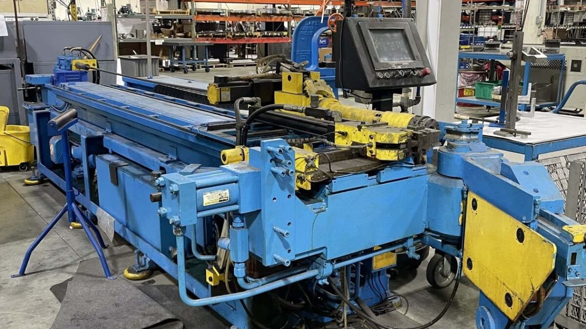
From Factory Floor to Your Workshop: Evaluating a Pre-Owned , Used , Secondhand, Surplus CNC Machines Before Purchase HMT Horn Machine Tools 1.6L CNC Tube Bender made in USA
Here’s a structured, machine-type–specific guide you can use when evaluating a used / surplus HMT Horn Machine Tools “1.6L CNC Tube Bender” (made in USA) before purchase. Because tube benders are a different class of CNC machinery (electro-hydraulic / servo / rotary axes, bending die systems, mandrels, tooling, bending radius control, etc.), some of the inspection points differ from a milling machine or lathe. Use this as your checklist from “factory floor to your workshop.”
I’ll break it down into: (1) what you should learn beforehand, (2) visual / static checks, (3) powered / dynamic tests, (4) tooling / bending test, (5) alignment / calibration / metrology checks, (6) estimating refurbishment costs & risks, and (7) red-flags / deal breakers.
1. Pre-Visit / Off-Site Preparation & Questions to Ask
Before you show up, you want as much information as possible so you know what “normal” is and can detect suspicious gaps.
| Item | Key Questions / What to Request | Why It Matters |
|---|---|---|
| Machine history & usage | How many years in use, how many bending cycles, hours of operation | High cycle counts stress tooling, hydraulics, mechanical components |
| Maintenance & service records | Records of hydraulic pump maintenance, servo motor replacement, controller servicing, hose / seal replacements | Good records show care; gaps or lack of records are a red flag |
| Past incidents / downtime | Any collisions, over-bending, tool crashes, hydraulics failure | Such events often cause hidden damage |
| Retrofit / upgrades | Has the control been replaced, any axis added, safety retrofits, software updates | Non-original components may be harder to support |
| Spare parts & tooling inventory | Are spare dies, mandrels, hydraulic hoses, servos, controllers, fittings included | Missing tooling / spares often cost more later |
| Control / software details | What CNC / control is used (brand, version), is the software original, are backups available | Control problems are often expensive to repair |
| Power / utilities requirements | Voltage, phase, hydraulic supply, coolant / lubrication lines, cooling requirements | Ensure your workshop can support the machine |
| Rigging & transport plan | How seller plans to move it, disassemble / reassemble, alignment, special lifting needs | Tube benders are large and have precision alignments to maintain |
| Inspection / test rights | Request ability to power up, jog axes, run sample bends, see control interface, load test | You want real-time diagnosis, not just photos |
| Warranty / acceptance clause | Can you reject or return it after installation if hidden problems arise? | Gives you leverage and reduces risk |
If the seller balks at providing these, be extremely cautious.
2. Visual / Static Inspection (Before Power)
Once you arrive, before energizing anything, walk around carefully and visually inspect mechanical, structural, and hydraulic systems.
A. Structure, Frame & Mechanical Components
- Inspect the main frame, bending arm, support columns, base for cracks, weld repairs, distortions, or misalignment.
- Inspect all covers, guards, panels, safety doors — missing, damaged, or poorly fitting covers often indicate past abuse or neglect.
- Examine hydraulic cylinders, arms, pivot points, linkages, pivot pins, bearings, shaft connections for wear, pitting, corrosion, oil leakage, or play.
- Check tie rods, torque arms, die support arms, clamps for bending, distortion, or cracked areas.
- Inspect hose / hydraulic lines, connectors, fittings — look for abrasions, swelling, leakage, makeshift repairs, mismatched hoses.
- Inspect cable routing, conduit, sensor cabling, interlocks, and cable carriers for signs of chafing, facture, non-OEM patches.
- Look at the tooling area: die clamps, mandrel supports, tool change mechanisms, guide rails — any damage or misalignment.
- Inspect servo motor housings, gearbox housings, coupling to axes, look for signs of oil leaks or damage.
- Examine the workpiece / feeding area (tube guide, rollers, feed clamps) — look for excessive wear, misalignment, bent guide rails or rails with corrosion.
B. Mechanical / Static Checks
- Try to move the bending arm or axes manually (if safe, with power off) to feel for binding, rough spots, or stiffness.
- Using feeler gauges, dial indicators, or small test gauges, check for play / backlash in pivot points, gearboxes, rods, linkages.
- Check the alignment or straightness of guide rails or bending axis — use a straightedge if available.
- Check actuator attachment points, bearing housings, and fasteners for looseness.
- Examine positive stops, limit switch hardware, and ensure none are bent or misadjusted.
- Verify hydraulic cylinders for internal leakage: apply a small manual force or displacement and see if it drifts — internal leak in cylinder is a hidden cost.
- Inspect tooling mounts, clamps, die seats, mandrel holders — check for wear, misfit, cracked shoulders, or misalignment.
If you see structural damage, bent linkages, cracked welds or misaligned frame components, that’s a serious negative and warrants deep discounting or stepping away.
3. Power-Up, Electrical, Control & Hydraulic Tests
After your static inspection is satisfactory, proceed to apply power carefully with all safety protections enabled. Then step through control and actuator tests.
- Observe control / CNC booting: the system should initialize cleanly, detect all axes / servo modules, and show no missing modules or I/O errors.
- Test all panel buttons, switches, emergency stop, indicators for responsiveness.
- In manual / jog / command mode, move each bending axis (if possible) slowly to confirm smooth motion, no jerkiness or stutter.
- Activate hydraulic pump and test hydraulic circuits with no load: watch for leaks, pressure stability, noise, vibration, or abnormal current draw.
- Test safety circuits: E-stop, limit switches, door interlocks, emergency stops — ensure none are bypassed.
- Confirm that servo / motor currents are within acceptable ranges (if you have instrumentation). Surges or overcurrent faults even under light load are red flags.
- Enable any limits, soft stops, zeroing homing routines to see whether axes can properly reference home.
- Test control software functions: command small movements, set bending angles, check parameter changes, confirm that the interface responds properly.
Any failure at this stage (control faults, drive errors, hydraulic instabilities) suggests deeper problems requiring expensive repair.
4. Dynamic Tests & Bending Trials
This is where the real performance emerges — under motion and load the weaknesses often come out.
A. Axis & Linkage Tests
- Command full travel of bending axes at multiple speeds (slow → medium → fast) and feel for smooth motion, absence of binding, unusual noises or vibration.
- Reverse direction at each axis and measure backlash / reversal error with a dial indicator or suitable instrumentation.
- Move to a target bend angle or position and command back and forth, checking repeatability of positioning.
- For multi-axis bending (if the machine has more than one bending axis), test coordinated motion or compound bending sequences to check synchronization.
B. Hydraulic / Pressure Tests
- Apply hydraulic pressure, observe how the machine holds pressure under load, check for leakage, drift, or pressure drop.
- While under hydraulic load, monitor behavior — any spiking or lag in response is suspicious.
- Cycle the hydraulic cylinders through extension / retraction several times while observing for delays, jerks, or abnormal behavior.
C. Bending / Test Part Trials
- Use a representative tube / pipe sample (material, diameter, wall thickness similar to your intended work) and perform one or more bend operations, including:
- Simple fixed-angle bends
- Multi-radius or compound bends
- Return bends or spring-back tests
- Measure the outcome: bend angle accuracy, repeatability, consistency, spring-back, straightness after bend.
- Test worst-case operations: tight radius bends, bends near tooling limits, long tube runs.
- Observe how material handling / feeding / guiding works during the bends (rollers, clamps, guides).
- Monitor if hydraulic pressure holds constant, whether the system behaves stably under full working load.
- After bending, measure and inspect tubes for distortion, ovality, surface finish, and any defects.
If the machine fails to reliably produce accurate, repeatable bends, that indicates serious wear or alignment errors.
5. Alignment, Calibration & Metrology Checks
If you have (or bring) inspection gear (gage blocks, indicators, optical tools), perform alignment checks and calibration of axes.
- Check geometric alignment of bending axis relative to base, guide rails, and feed axes. Any misalignment translates to bending error.
- Use indicators to check parallelism / perpendicularity of actuators, pivot arms, frames relative to base.
- Command precise angular / linear movements and measure actual vs commanded movement for scale errors or mapping deviations.
- Warm up the machine, then re-check alignment to detect thermal drift.
- At extremes of travel and bending range, verify that geometry still holds (i.e. the bending arm does not twist or deflect under full reach).
- Confirm that tooling die seats, mandrel positions, clamp positions are all aligned and not skewed.
Some misalignment can be compensated via shimming or software offsets, but structural deformation or twisted frames are expensive to fix.
6. Estimating Refurbishment Costs & Risk Buffer
Even a well-maintained tube bender will likely need refurbishment or parts replacement. Plan and budget carefully — here are common items and hidden risks:
- Hydraulic cylinder seals, rod wear / replacement
- Hydraulic pump / motor rebuild or replacement
- Servo motor / drive overhaul or electronics replacement
- Control system repairs, firmware, I/O modules
- Replacing hoses, fittings, valves, accumulators, pressure regulators
- Re-machining or aligning pivot arm bearings, mounts
- Replacing worn pivot pins, zerk fittings, bushings
- Refurbishing tooling holders, die clamps, mandrel holders
- Alignment work, calibration, shimming, test bending cycles
- Replacement or refurbishment of guide rails, slides, locking mechanisms
- Replacing sensors, limit switches, encoder feedback, angle sensors
- Upkeep / replacement of cable carriers, wiring harness, connectors
- Foundation / leveling, vibration isolation, rigging & transport
- Spare parts kit (seals, O-rings, hydraulic components)
- Contingency buffer (say 15–25 %) for unknown latent defects
Because a tube bending machine must produce consistent geometry under load, wear in even small components (pins, bearings, hose elasticity) can degrade repeatability. So don’t minimize small signs of wear.
7. Red Flags & Deal Breakers
During all these tests, certain findings should raise alarm bells (or lead you to walk away). Some of the top red flags include:
- Hydraulic leaks (visible or internal) that cannot be tracked easily
- Cylinders that drift, stick, or leak internally under test
- Erratic control behavior, drive faults, inability to command axes smoothly
- Excessive backlash, sloppy linkage, misalignment in bending arms
- Bent frames, weld repairs, structural damage in pivot arms or main frame
- Tooling holders, clamps, die seats that are damaged, misaligned, or worn
- Poor repeatability in bending tests (bends deviate significantly)
- Control electronics that appear obsolete, with no spares available
- Control or software that cannot load or program desired bending paths
- Excess deviation from expected specification (range, angle, tube diameter) without explanation
- Lack of ability to test or trial bending under real conditions
- Unwillingness of seller to provide documentation, or to offer acceptance / return window
If you encounter multiple red flags, the risk rises steeply. Demand discounts, or consider walking away.