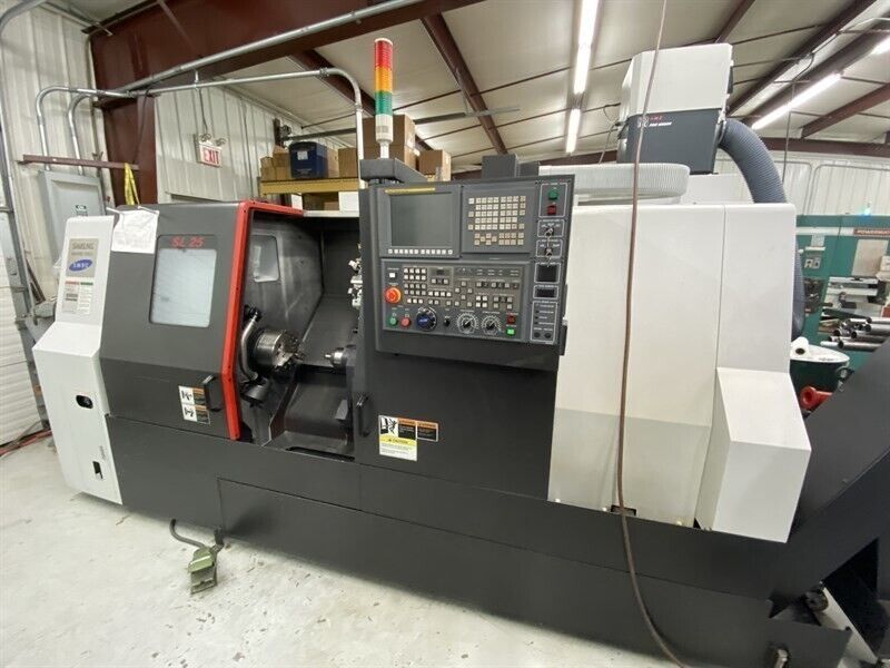
From Factory Floor to Your Workshop: Evaluating a Pre-Owned , Used , Secondhand, Surplus CNC Machines Before Purchase Samsung SL-25 1000 CNC Lathe made in South Korea
Here’s a full “Factory Floor → Workshop” evaluation guide for a Samsung SL-25 / SL-25 1000 CNC lathe (South Korea origin) — covering reference specs, inspection steps, test routines, and decision criteria. Use this when considering a used / surplus example of that machine.
1. Reference Specs & Benchmark Data (What to Expect)
To know what “normal” looks like for an SL-25 / SL-25/1000, here are published specs and ranges you can use as a baseline for comparison:
| Spec | Typical / Published Value | Source / Notes |
|---|---|---|
| Chuck Size | 10″ (≈ 254 mm) | “Chuck Size 254 mm” |
| Bar Capacity / Bore | ~ 3.03″ (~ 76.9 mm) | Same listing: “Bar Capacity 76.962 mm” |
| Max Spindle Speed | 3,500 rpm | MachineTools listing: “Max RPM 3,500 RPM” |
| Horsepower / Power | ~ 22.4 kW | Power 22.4 kW |
| Turning / Swing | Swing 518 mm; Machining diameter ≈ 378 mm | From MachineTools: “Turning Dia 378.46 mm”, “Swing 518.16 mm” |
| Work Length / Center Distance | ~ 1,016 mm | “Machining Length 1,016 mm” |
| Control | Fanuc 0i-TD (or variant) | MachineTools listing notes control = Fanuc 0i-TD |
| Axes | 2 axes (X + Z) as standard | MachineTools listing: “# Axis 2” |
Because the SL-25 (or SL-25/1000) is an older but solid turning center, many units may have been upgraded or modified; always check actual values against what is claimed.
Also, note related model listings such as “SL-25B 1000” which show:
- Swing 20.4″ (≈ 518 mm)
- Swing over cross slide: 13.8″ (≈ 350 mm)
- Max machining diameter: 14.9″ (≈ 378 mm)
- Center distance / working length: 40.0″ (≈ 1,016 mm)
- Spindle speed: 3,500 rpm
- Motor power ~ 30 hp in some ads
These help you set expectations and suspicious claims.
2. Pre-Screening & Documentation You Should Request
Before going to the machine’s location, gather as much documentation and data as possible. This helps you plan the inspection and identify glaring red flags early.
Ask the seller to provide:
- Clear photographs of nameplates / plates (mechanical, electrical) showing model, serial number, year
- Original spec sheet / user manual / parts catalog for that exact SL-25 variant
- Details of the CNC / control system (manufacturer, version, any upgrades)
- Inclusive parts list / spare control modules / electronics included
- Usage history (hours, types of parts, duty cycle)
- Maintenance / repair history (spindle rebuilds, guideway repair, turret repair)
- Pictures / video of the machine in operation (axis jogging, tool changes, spindle running)
- Reason for sale (upgrade, relocation, failure)
- Shop environment (dust, coolant, chip buildup, etc.)
- Foundation / rigging information (machine weight, footprint, how it was anchored)
If the seller is evasive or cannot provide many of these, treat it as a caution sign.
3. On-Site Structural & Mechanical Inspection
When you reach the site, bring metrology tools (dial indicator, test bar, squares, feeler gauges) and ideally an experienced technician. Proceed systematically:
3.1 Structural / Visual Walkaround
- Check the bed, base, column / frame, casting integrity, any signs of weld repairs, distortions
- Inspect guideways, lead screws, slides (X, Z axes) for pitting, wear, corrosion, scoring
- Examine way covers, bellows, guards for tears, missing sections or misalignment
- Inspect spindle housing, nose, taper for nicks, wear, and whether the face is clean
- Check the tool turret / turret face, indexing face for wear, slop, damage
- Inspect wiring, conduits, cables, junction boxes for patched wires, exposed insulation, sagging cables
- Look for coolant / lubricant leaks around seals, scuppers, base pans
- Examine the work table / chuck mounting surface for wear, alignment, mounting integrity
If possible, carefully jog axes manually (in manual / slow mode) to see if any zones feel rough or bind.
3.2 Motion, Backlash & Kinematics Tests
- Jog X and Z axes slowly through their full strokes; feel for nonuniform motion, sticking zones
- Place a dial indicator to measure backlash / lost motion (push-pull) in X and Z axes at a few positions
- Reverse direction near endpoints to detect hysteresis or deadband
- Check drive screws, nut coupling, slide bearings, couplings for loose play
- Move small incremental steps to verify consistent response and no slipping
- Cycle turret or tool indexing (if present) multiple times to check for sluggishness, mis-indexing, or wear
3.3 Spindle, Tooling & Turret Tests
- Power the spindle (if safe) across speeds; monitor for bearing noise, vibration, irregularities
- Use a test bar + dial indicator to measure runout at spindle nose (and along bar length if possible)
- Observe spindle acceleration / deceleration behavior (should be smooth)
- Inspect the taper, mounting faces, chuck / backplate interface for damage or wear
- Operate the tool turret / tool changer: observe tool insertion / ejection, indexing, clamping force
- If the machine has a C-axis (turning with rotational positioning), test the C-axis indexing precision
3.4 Control & Electrical / CNC Cabinet Inspection
- Open CNC / electrical cabinets, check wiring, fuses, connectors, terminal blocks
- Look for heat damage: discoloration, burnt connections, melted insulation
- Check servo drives, amplifier modules, interface boards for signs of corrosion or damage
- Examine cable routing, shielding, strain relief integrity
- Power up: test buttons, switches, emergency stop, door interlocks
- Navigate the CNC interface: inspect parameter sets, tool tables, offsets, alarm logs
- Test safety interlocks (door open should stop motion)
- If the machine has feedback encoders or linear scales, test their readings and consistency
4. Operational / Test Cuts Under Load
If the seller allows, real machining is one of your strongest verification methods.
- Run a dry / air movement program (no material cut) exercising axes, tool changes, turret moves
- Perform a test cut in a known / mild material (e.g. aluminum or mild steel) to study surface finish, chatter, dimensional accuracy
- Run a continuous cycle (30–60 minutes or more) under moderate load; after running, remeasure backlash, offsets, geometry to detect thermal drift
- After warm-up, repeat earlier measurements (backlash, runout) to see if behavior has shifted
- Cycle tool changes and turret indexing multiple times to test for repeatability, slop, or wear over cycles
Watch for deviation, drift, chatter, or errors mid-cycle.
5. Metrology, Accuracy & Drift Verification
- Use calibrated gauge blocks, test bars, or master fixtures to assess straightness, squareness, alignment
- Conduct a repeatability / reversal test: move to a reference point, retract, return, measure deviation
- On test-parts, measure dimensional fidelity, roundness, flatness, tolerance adherence
- After prolonged cutting, re-check offsets, backlash, alignment for drift
- Compare your measurements vs your required tolerances and against typical values for such machines
6. Infrastructure, Installation, and Practical Considerations
- Confirm your shop floor’s load capacity is adequate for the machine
- Check the crane / rigging access, paths, door / ceiling clearances for moving the machine
- Validate your power supply (voltage, current, phase) aligns with machine requirements
- Ensure coolant / lubrication / chip removal / filtration / ventilation systems are adequate
- Prepare for leveling, foundation, anchoring, grouting as needed
- Confirm access around the machine for maintenance (rear, cabinet, slides, turret)
- Ensure the availability of spare parts (bearings, drives, turret parts, control modules) for Samsung / SL series machines
7. Decision & Negotiation Criteria / Red Flags
After your inspection and testing, evaluate using these decision criteria:
Positive / Acceptable Indicators:
- Measured travels, spindle speeds, swing, etc. closely match claimed specs
- Smooth, consistent axis motion, low backlash, repeatable response
- Spindle operates quietly with minimal vibration, acceptable runout
- Tool turret / indexing is reliable and precise
- CNC / control system is healthy, no burnt modules, good logs
- Test cut yields good surface finish and dimensional stability
- Accuracy stable after warm-up (minimal drift)
- Spare parts, documentation, tooling are included or available
Red Flags / Deal-Breakers:
- Significant mismatch between claimed and actual specs (travel, rpm, power)
- Heavy wear on guideways, binding zones, inconsistent motion
- Spindle noise, vibration, excessive runout
- Turret mis-indexing, tool seating errors, slop
- Burned / damaged control / electrical modules, wiring problems
- Test cuts show drift, chatter, poor tolerance performance
- Behavior shifting significantly after warm-up
- Lack of critical spare parts or obsolete modules
- Seller refusing test operations, measurements, or documentation
Use any defects or mismatches you discover as leverage in negotiation — demand spare parts, discount, contract for refurbishment, or acceptance trials (e.g. machine must pass a test program before final payment).
Because SL-25 machines are more common than some, you may have a better chance at finding parts or refurbished components; still, insist on proof of performance and documented condition.