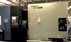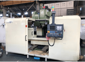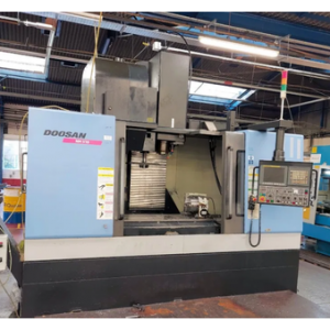
From Factory Floor to Your Workshop: Evaluating a Pre-Owned , Used , Secondhand, Surplus CNC Machines Before Purchase Doosan NM 510 CNC Vertical Machining Center made in South of Korea
Here’s a structured, in-depth evaluation guide (from “factory floor → your workshop”) for assessing a pre-owned / used / surplus Doosan NM-510 vertical machining center (South Korea origin). Included are reference specs, inspection steps, test procedures, and decision criteria to help you evaluate whether it’s worth buying (or walking away).
1. Reference Specs & What to Expect (Benchmarks)
Knowing typical specifications for the NM -510 (or “MYNX NM-510”) lets you spot exaggerations or red flags in the seller’s claims. Below are representative specs collected from multiple used machine listings:
| Specification | Typical / Published Value | Notes / Sources |
|---|---|---|
| X / Y / Z travel | 1,020 mm × 510 mm × 510 mm | Many listings: X = 1,020 mm, Y = 510 mm, Z = 510 mm |
| Table size / work area | 1,200 mm × 500 mm | Auction listings: table = 1,200 × 500 mm |
| Max spindle speed | 12,000 rpm | Common in machine ads: 12,000 rpm BT40 spindle |
| Spindle taper / tool interface | BT-40 (ISO / DIN style) | Multiple sources state BT40 taper |
| Spindle motor / power | ~ 11 kW (continuous) / up to ~15–18.5 kW in some models | Listings: 11 kW continuous, or 15/18.5 kW in variant versions |
| Table load / workpiece weight | ~ 800 kg maximum | Auction listing states “workpiece weight max 800 kg” |
| Rapid traverse / feed rates | ~36 m/min in X/Y, ~30 m/min in Z in some listings | Some ads indicate rapid moves of 36 / 36 / 30 m/min |
| Tool magazine / capacity | ~ 30 stations | Auction specs: 30-station ATC included |
| Control / features | Fanuc 0i-MC / 4th axis interface / through-spindle coolant / chip conveyor | Auction listing: Fanuc Oi-MC, 4th axis, coolant through spindle, conveyor |
These numbers are your “safe envelope.” If a seller claims, say, 2,000 mm X travel, 20,000 rpm spindle, or impossible load ratings without evidence, demand proof or treat those claims skeptically.
2. Pre-Visit & Documentation Request (Before Going On-Site)
Before you invest travel time, get as much documentation and data as possible to pre-filter and plan your inspection.
Request / verify:
- Nameplate / ID photos
• Machine mechanical nameplate (model, serial, year)
• Electrical / control cabinet nameplate (voltage, phases, current ratings) - Specification sheets / manuals
• The original NM-510 or MYNX NM-510 technical data sheet
• Control / CNC manuals, spare parts list, wiring diagrams - Control & CNC data
• Which controller (Fanuc 0i-MC, possibly upgrades)
• Software version, parameter backups, axes offsets, tool tables - Operating / usage history
• Total running hours, cutting / load hours vs idle
• Types of materials processed, workloads (e.g. heavy cuts, high speed, finishing) - Maintenance / repair history
• Spindle rebuilds, bearing replacements, guide rework, linear slide repairs
• Any modifications or retrofits (e.g. adding 4th axis, coolant upgrades) - Accessories / tooling / spares included
• Chucks, fixtures, tool holders, probes, extra control modules
• Spare parts (drives, motors, electronics) included or available - Photos / video in operation
• Axis jogs, tool changes, spindle running, chip flow
• Close-ups of guideways, spindle nose, electronic cabinets - Reason for sale
• Is it being replaced, retired, or due to failure? - Shop / environment
• How clean was the facility? Dust, coolant, coolant tramp oil, chip management
• Ambient temperature control, ventilation - Installation / rigging data
• Machine weight, footprint, foundation, crane access, path to remove / install
If the seller refuses or cannot supply many of these, that is a red flag.
3. On-Site Mechanical & Structural Inspection
Bring precision instruments (dial indicator, test bar, straightedge, feeler gauges). If possible, bring or consult someone experienced with machining centers. Work systematically:
3.1 Structural / Visual Examination
- Inspect machine frame, base, column / bridge for cracks, weld repairs, distortions, sagging
- Examine guideways / linear rails / sliding surfaces (X, Y, Z) for pitting, wear, corrosion, scoring
- Check way covers, bellows, protective guards—tears, missing pieces, poor installation
- Inspect spindle housing, spindle nose, taper surfaces for nicks, dents, wear
- Check the tool changer mechanism / magazine for mechanical wear, broken fingers, misalignment
- Inspect wiring, cables, conduits, cable carriers for patched wires, exposed insulation, slack or bending
- Look for coolant / lubricant leaks around seals, ways, pump housings
- Check the table / pallet surface for flatness, damage, mounting hole integrity
If possible, manually (or jog slowly) move axes to detect sticking spots or roughness.
3.2 Axis Motion, Backlash & Kinematic Tests
- Move each axis (X, Y, Z) slowly through full travel; feel for smoothness or zones of resistance
- Use a dial indicator to measure backlash / lost motion (push / pull) for each axis at multiple positions
- Reverse direction near limits to detect hysteresis or dead zone
- Inspect ball screws, nuts, couplings for slack, play, side motion
- Move in very small increments to test repeatability and look for creeping or stepping
- Cycle tool changes / indexing (if applicable) repeatedly to observe slop, mis-indexing, wear
3.3 Spindle and Tooling Inspection
- Run the spindle (if permitted) at several speeds: listen / feel for bearing noise, vibration, hum
- Use a test bar + dial indicator to measure runout at spindle nose and along the bar if possible
- Check spindle acceleration / deceleration behavior
- Inspect taper surfaces, mounting seats, chuck / fixture interfaces for wear or damage
- Operate the tool changer / magazine: tool pick / placement, clamping action, indexing precision
- If the machine has optional 4th axis, test indexing / accuracy of that axis as well
3.4 Control, Electrical & CNC Cabinet Review
- Open control and power cabinets; inspect wiring, fuses, relays, connectors, modules
- Look for signs of overheating: discolored insulation, charred connectors, melted parts
- Inspect servo drives, amplifier cards, interface boards for damage, dust, corrosion
- Check cable routing, shielding, strain relief, plug integrity
- Power up: test buttons, switches, emergency stops, limit / safety interlocks
- Browse the CNC interface: parameter memory, tool tables, offsets, alarms, error logs
- Test safety interlocks: opening doors / guards must disable motion
- If the machine has encoders / linear scales, test their responses for consistency
4. Operational / Machining Test Under Load
If allowed, doing real cutting tests is one of your strongest validation steps.
- Run a dry / air motion program (no cutting) that exercises all axes, tool changes, indexing
- Perform a test cut (in stable material like aluminum or mild steel) to inspect surface finish, dimensional accuracy, chatter
- Run a sustained machining cycle (e.g. 30–60 min) under a moderate load; after running, remeasure axes, offsets, check for drift
- After warm-up, revisit earlier measurements (backlash, runout) to see if behavior changed
- Cycle tool change many times under load to test repeatability, wear, reliability
Look for deviations, thermal drift, anomalies mid-cycle.
5. Precision, Metrology & Drift Checks
- Use gauge blocks, precision test bars, or reference artifacts to assess straightness, squareness, alignment
- Perform repeatability / reversal tests: move to a point, retract, return, measure deviation
- Inspect test parts for dimensional fidelity, geometric errors (flatness, parallelism, circularity)
- After extended operation, re-measure offsets, backlash, alignment for shift or drift
- Compare measured errors vs your part tolerance requirements and against the benchmark expectations
6. Infrastructure & Installation Considerations
- Confirm your workshop’s floor load capacity for the machine’s weight
- Check crane / rigging / removal pathways, door heights, floor flatness
- Validate your power supply (voltage, current, phases) matches machine needs
- Ensure coolant / chip removal / filtration / coolant tank condition are adequate
- Plan for correct leveling, anchor bolts, foundation preparation
- Ensure access space around all sides (electrical, maintenance, spindle, tool changer)
- Confirm availability of spare parts (bearings, drive modules, tool changer parts) for NM / Doosan series
7. Decision Criteria, Red Flags & Negotiation Leverage
Once you have all data, here’s a rubric to help you decide:
Positive / Acceptable Indicators
- Measured travels, rpm, power are close to advertised specs
- Motion is smooth, backlash low, repeatable performance
- Spindle runs quietly, vibration is low, runout within acceptable bounds
- Tool changer is reliable and precise; indexing is consistent
- Control / CNC system is functional, clean, no burned modules or error logs
- Test cuts yield good surface finish, dimensional fidelity
- Stability after warm-up (minimal drift)
- Spare parts, tooling, documentation included or readily available
Warning / Deal-Breaker Indicators
- Major mismatch in claimed vs measured spec (e.g. travels, rpm)
- Heavy wear on guideways, binding, inconsistent motion
- Noisy, vibrating spindle; large runout
- Tool changer mis-index, slop, erratic behavior
- Burned, missing, or damaged electronic modules; corrupted memory
- Test cuts show drift, chatter, dimensional deviations
- Behavior changes significantly after warm-up
- Critical spare parts not available or proprietary / difficult to source
- Seller refuses to allow test cuts, measurements, or provide documentation
Use any defects or mismatches you observe as negotiation leverage — ask for replacement parts, discount, guarantee, or additional warranties. Because Doosan machines tend to have relatively good parts support, that gives you some confidence, but you should still insist on proof, documented acceptance tests, and condition guarantees.