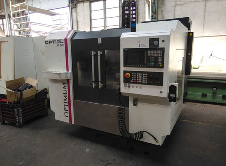
From Factory Floor to Your Workshop: Evaluating a Pre-Owned , Used , Secondhand, Surplus CNC Machines Before Purchase OPTIMUM Optimil F 150 CNC Vertical Machining Center made in Germany
Here’s a structured, detailed guide (from “factory floor to workshop”) for evaluating a pre-owned / used / surplus OPTIMUM “Optimil F 150” (aka OPTImill F 150 / F150E / F150 HSC) vertical machining center, which is built in Germany. Use this as your inspection blueprint, and adapt it to the particular variant you’re inspecting.
1. Background & Reference Spec Data
Before you visit, get familiar with the typical specs and features for the OPTIMUM / OPTImill F 150 series. That way you know what to expect (or what might indicate exaggeration / hidden modifications).
Some published data:
| Feature | Typical / Published Value | Notes / Source |
|---|---|---|
| Manufacturer / Origin | Germany (Optimum Maschinen GmbH) | Their product literature / catalogues refer to “Optimum Maschinen Germany” |
| Control System | Siemens SINUMERIK 828D (or variants) | Many listings of F150 / HSC models show this control |
| Travels (X / Y / Z) | ~ 750 mm / 500 mm / 500 mm | Example listing: F150E: X = 750 mm, Y = 500 mm, Z = 500 mm |
| Table size / load | ~ 900 × 500 mm, table load ~ 350 kg | A listing gives those values for the F150E model |
| Spindle speed / taper | Up to 10,000 RPM (for F150E variant) | For F150E listing, spindle 10,000 rpm, BT40 taper |
| Accuracy / repeatability | ± 0.005 mm | A used listing for the HSC version claims repeat / positioning accuracy ± 0.005 mm |
| Rapid traverse speeds | Up to ~ 30,000 mm/min (i.e. 30 m/min) | In a used listing, feed / rapid moves up to 30,000 mm/min are given |
| Machine weight / dimensions | Several tonnes; footprint ~ few meters | Example: ~ 4.4 t weight, machine dimensions ~ 4,5 × 2,8 × 2,5 m in one listing |
These specs are helpful to cross-check what the seller claims. If the seller’s “F 150” deviates heavily (e.g. claims 20,000 rpm or 1,500 mm travel) without proof, treat with suspicion.
Also, download or ask for the original OPTImill F 150 operating manual (which is available online) to compare wiring diagrams, mechanical layouts, etc.
2. Pre-Screening & Documentation Review
Before you go onsite, request or inspect these documents and data. A good seller should provide much of this.
| Document / Info | Why It Matters | What to Check / Ask |
|---|---|---|
| Nameplates (mechanical, electrical) & serial numbers | Confirms model variant and helps you trace parts or drawings | Ask for clear photos showing all the plates |
| Specification sheets / brochures | You can compare claimed specs to your reference specs | Make sure the variant matches (F150, F150E, HSC variant, etc.) |
| Electrical wiring diagrams, control schematics | To verify wiring integrity, modifications, and future repairability | Check whether schematics match what is physically wired |
| Control system version / software / parameters | Ensures the CNC is intact and not heavily modified or corrupted | Request a backup of the control parameters (if possible) |
| Usage / runtime / cutting hours | Shows how much wear the machine has endured | Distinguish between “powered-on” hours and actual cutting hours |
| Maintenance & repair history | Reveals how well the machine was cared for, and major past repairs | Spindle rebuilds, guideway reconditioning, control board replacements |
| List of tools / accessories / spares included | Adds value; may reduce your risk | Probes, fixtures, extra tool holders, spare electronics |
| Photos / video in operation | Gives you a first impression: motion, wiring, ergonomics, etc. | Ask for video of the spindle running, axes moving, tool changes |
| Reason for sale | To understand whether it is being sold because of end-of-life, malfunction, or upgrade | Ask directly whether any problems are known |
| Shop / environment details | Helps you anticipate how dirty / dusty / harsh the conditions were | Was it in a heavy-production environment, a clean toolroom, or near cutting fumes? |
If the seller is evasive or cannot provide many of these, treat that as a red flag.
3. On-Site Inspection & Mechanical Assessment
Once on location, bring your measuring tools (dial indicators, test bars, micrometers) and—if possible—a trusted machinist/technician. Use a consistent, logical inspection order.
3.1 Visual & Structural Inspection
- Examine the bed / base / cast structure for cracks, repairs, welds, distortion
- Inspect guideways / linear rails / slides in X, Y, Z axes for pitting, corrosion, scoring, uneven wear
- Check way covers, protective bellows, guards—are they intact, or torn / patched?
- Inspect spindle head, column, housing—note any surface damage, misalignment signs
- Look for signs of coolant leaks, oil seepage, dried residue—especially around seals and sliding surfaces
- Inspect wiring, conduits, protective covers, cable carriers—look for damage, splices, patches
- Check tool changer / magazine: presence, condition, kinematics, mechanical integrity
- Examine coolant system (tank, pump, piping), chip conveyor, filtration systems
At this stage, you may not be able to confirm functionality, but you can spot neglect, abuse, or poor maintenance.
3.2 Kinematics & Motion / Backlash Tests
- With the machine powered off or in safe mode, manually (or slowly) move each axis to feel for binding, “notchiness,” or stiction
- Use a dial indicator to measure backlash / lost motion in each axis (X, Y, Z), ideally at multiple positions along travel
- Reverse direction at endpoints to detect hysteresis / deadband
- If possible, command slow axis motion and observe consistency (no jumps, jerks)
- Inspect ballscrews / linear guides / nuts / couplings for looseness or wear
- Cycle tool changer several times (if accessible) and check for mis-indexing, hesitation, mechanical play
3.3 Spindle, Drive & Tooling Inspection
- Power up the spindle and run at various speeds (low, medium, high)—listen closely for noises (rattle, bearing hum, irregular tones)
- Use a test bar + dial indicator to check spindle runout at the nose and over length
- Monitor spindle bearings’ temperature during operation if possible
- Check the spindle’s acceleration / deceleration performance
- Inspect the spindle nose, taper area, clamping surfaces for damage or misalignment
- If there is a through-spindle coolant option, inspect its seals, plumbing, and whether it holds pressure
- Check tool changer / tool magazine operation under manual commands: does it pick/place reliably, with consistent alignment
3.4 Control / Electrical / Cabinet Inspection
- Open the electrical / control cabinets and inspect: wiring, junction blocks, relays, fuses, terminal strips
- Look for discoloration, burnt wiring, overheating marks, melted insulation
- Check cable routing, shielding, strain reliefs, and protective conduits
- Power on the CNC / control panel: test all buttons, switches, override knobs, emergency stop, limit switches / interlocks
- Navigate the control’s menus and check parameter memory, offsets, tool tables, alarm logs
- Verify safety interlocks: door open → motion stops, limit switches, E-stop circuits
- Check grounding, noise suppression, and power stability
4. Operational / Performance Testing (Live Tests)
If the seller allows, performing live tests under motion and load is among the most revealing steps.
- Perform a dry run (no cut) of a programmed path (include X, Y, Z moves, tool changes, simple shapes) and observe movement consistency
- Execute a test cut in a moderate, familiar material: check surface finish, dimensional accuracy, chatter
- Conduct a longer cycle (30–60 min) under moderate load; recheck critical measurements afterward to detect thermal drift or shift
- After warm-up, measure backlash, alignment, runout again to see if deviations changed
- Repeat motion sequences (go to a point, retract, return) multiple times to test repeatability
- Cycle the tool changer repeatedly under command to check reliability
- Test boundary / limit moves (travel extremes) carefully to see if axes maintain performance near edges
5. Precision / Metrology Checks
Because a machining center needs precise geometry, include the following:
- Use calibrated gauge blocks, test bars, or surface plates to verify straightness, squareness, flatness
- Check repeatability / reversal error: move to a reference point repeatedly and measure deviation
- Check runout / concentricity of turned or milled workpieces
- Re-measure after warm-up to detect thermal drift (changes in geometry as the machine heats)
- Check how the tool height / offset is preserved over tool changes
- Compare your measured tolerances with your workshop’s requirements and with published specs (e.g. ±0.005 mm or better)
6. Infrastructure, Rigging & Installation Constraints
- Check the floor’s load-bearing capacity; these machines are heavy
- Confirm crane / rigging / machine removal access, overhead clearance, door sizes
- Verify your workshop’s power supply (voltage, phase, current) matches or can be upgraded
- Check whether coolant, chiller / temperature control, chip removal (conveyor or coolant return), ventilation are sufficient
- Confirm you can access all sides of the machine for maintenance
- Evaluate foundation and leveling needs—those must often be redone
- Check safety guarding, perimeter clearance, and service access
7. Post-Inspection Evaluation & Decision Criteria
Once your inspection is done and you have measurements, video, and observations, use this checklist to decide or negotiate:
| Category | Good / Acceptable Signs | Red Flags / Deal Breakers |
|---|---|---|
| Alignment / Geometry | Slight positional deviations within tolerance; repeatability good | Large drift, especially after warm-up; inconsistent direction errors |
| Backlash / Motion quality | Backlash within acceptable bounds; smooth motion | Excessive backlash, stick-slip, gritty motion |
| Spindle health | Quiet operation, low runout, stable under load | Bearing noise, vibration, high runout, warm bearings |
| Tool changer / magazine | Reliable, consistent tool change, no mis-indexing | Tool drop, mis-index, inconsistent alignment |
| Control / electronics state | Clean wiring, stable control, good diagnostics | Burnt wires, failing modules, inconsistent control behavior |
| Operational test success | Good surface finish, stable machining, no chatter, dimensional adherence | Chatter, poor finishes, dimensional drift during run |
| Thermal / drift stability | Geometry holds after warm-up | Significant dimensional shift after heat-up |
| Repair / refurbishment cost | Issues are known and repairable, key parts available | Unknown or unavailable parts, major structural damage |
| Parts & support availability | Spare electronic / mechanical parts locally available or from the OEM | Obsolete modules, long lead times, unsupported control |
| Negotiation leverage | Use defects found to reduce price, demand spares or guarantee | Seller refuses to provide proof or accept known defects |
| Warranty / performance guarantee | Ability to get “performance guarantee” or test-cut guarantee | “Sold as is” with no recourse for hidden defects |
In negotiations:
- Insist on including spare parts (e.g. drive modules, relays, wiring harnesses)
- Ask for a short-term performance guarantee (e.g. 30–90 days)
- Use actual test-cut data as proof of machine capability
- Demand seller responsibility for rigging / transport / leveling costs, especially if defects are found
- Document everything (photos, measurement logs) as reference or recourse