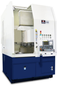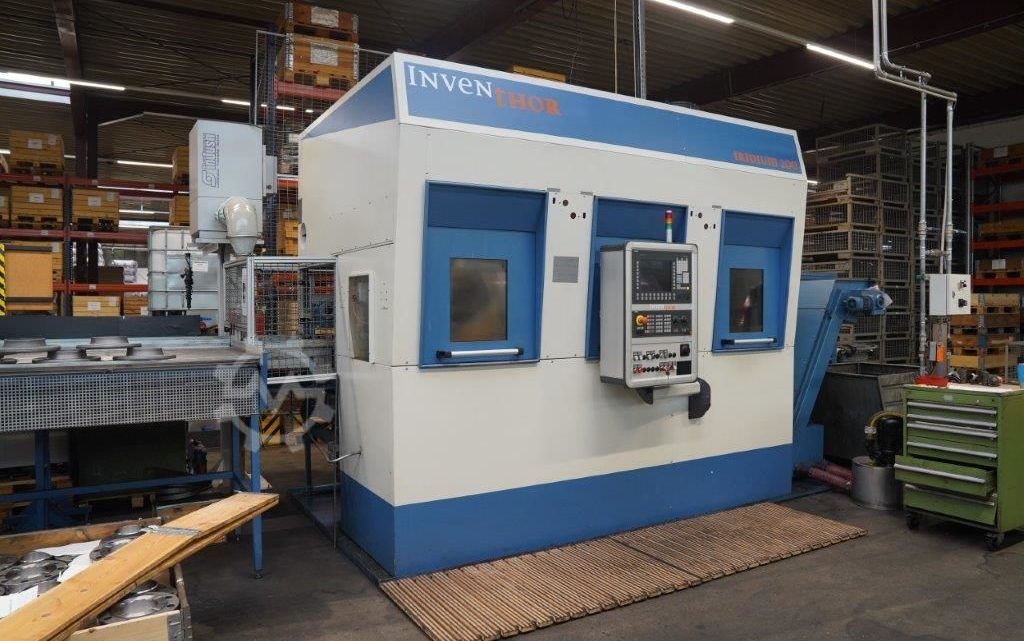
From Factory Floor to Your Workshop: Evaluating a Pre-Owned , Used , Secondhand, Surplus CNC Machines Before Purchase INVENTHOR IRIDIUM 200 CNC Vertical 2 Spindles Lathe made in Germany
Here’s a tailored “Factory Floor → Workshop” style evaluation guide for a pre-owned / surplus Inventhor Iridium 200 (2-spindle vertical CNC lathe, Germany) — what to check, test, and measure to minimize your risk. I’ll also share known specs / data to help you benchmark the machine you’re inspecting.
Known / Reference Info & Spec Benchmarks for Inventhor Iridium 200
It helps to start with what the manufacturer advertises or what used machine listings show, so you can validate claims and detect exaggerations.
From available sources:
- The Inventhor Iridium 200 is a vertical turning (vertikal-drehmaschine) with 2 movable main spindles, designed for serial production with parallel workpiece change.
- One used listing (Hommel GmbH) gives technical data for an Iridium 200:
• Spindle nose size: A6 (DIN 55026) with Schunk D260 mm chucks
• Maximum RPM: 4,500 rpm
• Drive power: 12.5 kW per spindle
• Maximum turning length: 150 mm (workpiece length)
• Maximum turning diameter (each spindle): 250 mm
• Tooling: Each spindle is fitted with a cross slide (X & Z axes) and tool turret with VDI40 tool holders (8 stations)
• Workpiece feeder / automation: belt / table system for part loading/unloading, part buffer table for ~30 flanges of Ø200 mm, ~150 kg capacity - The manufacturer’s site describes that the Iridium 200 is a 4-axis vertical lathe with two movable main spindles and parallel piece changing (main machining and workpiece transfer happen in parallel) to enhance throughput.
These are your reference numbers. If you see claims such as 8,000 rpm, 500 mm part length, or 20 kW spindles without documentation, treat them skeptically and demand proof.
Pre-Screening / Documentation Review (Before On-Site Visit)
Before going in person, collect as much info and documentation as possible. A good seller should be able to provide these:
| Item | What to Request / Verify | Why It’s Important |
|---|---|---|
| Photos of nameplates (mechanical & electrical) | To confirm model, variant, serial, manufacturing date | Helps validate when mismatches occur |
| Full spec sheet / brochure / operating manual | To compare claimed vs original design | See what the machine was built to do |
| Control / CNC system details | Model (e.g. Siemens 840D?), software version, backup, parameter files | Control health and maintenance risk |
| Operating hours / usage history | Power-on vs cutting / spindle hours | Indicates wear, service intervals |
| Maintenance / repair records | Spindle rebuilds, axis rework, replacement of wear parts | Helps estimate future cost |
| List of accessories / tooling / spare parts | Turrets, chucks, pallets, backup electronics | Adds value and mitigates risk |
| Videos / photos of the machine in operation | Axis movements, spindle running, load/unload cycles | First look at what “working” looks like |
| Explanation of configuration (2 spindles, automation, tooling layout) | Especially how dual spindles and transfer logic work | Critical to understand the machine flow |
| Reason for sale | If the machine is being sold because of failure, idle, or shop closure | Gives insight into hidden problems |
| Facility / environment details | Cleanliness, coolant type, chip build-up, humidity | Bad environment accelerates degradation |
| Layout / rigging / weight / footprint | Machine floor plan, foundation needs, crane access | For planning relocation and installation |
If the seller is unwilling or unable to provide these, consider it a red flag.
On-Site Inspection & Mechanical / Structural Assessment
Bring measuring tools (dial indicators, test bars, calipers) and ideally a machinist with experience in vertical turning / dual-spindle systems. Proceed from external to internal, static to dynamic.
1. Visual / Structural / Exterior Inspection
- Inspect the machine frame / base / column for cracks, welds, distortions, or modifications.
- Check guideways / slide surfaces (for the X, Z axes on both spindles) for scoring, corrosions, wear marks, pitting, or uneven wear.
- Examine way covers, guards, bellows: missing or damaged covers allow contamination.
- Inspect spindle heads, tool turret housing, spindle nose / taper surfaces for damage, nicks, or misalignment.
- Check wiring, conduits, cable chains, junction boxes for patched wires, exposed insulation, fatigued cables.
- Look for coolant / oil leaks near sliding surfaces, around seals, valves, pumps.
- Examine the part transfer mechanism / automation elements: belts, feeders, buffer tables, grippers, transfer arms — look for wear, play, misalignment.
Where safe, gently jog axes or manually move components (in safe mode) to sense binding or rough segments.
2. Axis / Motion / Backlash Checks
- Jog each axis (X & Z axes for both spindles, plus any transfer axes) slowly through full travel: feel for smoothness, binding, irregular zones.
- Use dial indicators or test indicators to measure backlash / lost motion in each axis (push-pull) at various positions.
- Reverse direction near endpoints to detect hysteresis or deadband.
- Check ball screws, nuts, couplings, bearings for looseness or play.
- Jog with slow feed and observe motion consistency, look for jumps or hesitation.
- Repeat tool turret indexing and part transfer cycles several times to check for repeatability deterioration or mis-alignment.
3. Spindles, Chucks, Tooling, Transfer Mechanism
- Power up spindles (one at time) and run at multiple speeds, listening carefully for bearing noise, vibration, hum, unusual resonances.
- Use a test bar + dial indicator to measure spindle runout at the nose (and ideally at a few points along length).
- Check spindle acceleration / deceleration behavior; see whether it responds cleanly.
- Inspect chuck mounting surfaces, clamping mechanisms, jaws, backplates for wear or damage.
- If tool turrets are present, command index operations: verify indexing speed, repeatability, absence of mis-indexing or lag.
- Operate the part transfer mechanism (gripper, belt, linear slide) in motion (if possible) to check smoothness, alignment, positioning accuracy, and mechanical play.
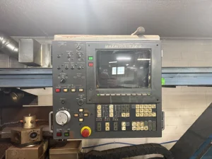
4. Control / Electrical / Cabinet / Electronics
- Open control and power cabinets; thoroughly inspect wiring, terminal blocks, fuses, relays, drive modules, PCB boards.
- Look for signs of overheating: discoloration, burnt wires, melted insulation, scorched terminals.
- Inspect servo / amplifier modules, interface cards, power supplies for corrosion, damage, or signs of past failure.
- Check cable routing, strain reliefs, shielding.
- Power up the control: test all switches, knobs, emergency stops, limit switches, interlocks.
- Navigate CNC interface: check parameter memory, tool tables, error logs, backups.
- Verify safety interlocks: opening doors / guards should cease motion immediately.
- If linear scales or encoders are installed, test whether their readings are functioning.
Operational / Test Cut & Live Testing
If the seller allows, performing test cuts and running under load is crucial to detect behavior not evident under idle or axis-only motion.
- Conduct a dry / air run (no cut) that exercises all axes, part transfer cycles, spindle starts / stops, tool turret indexing.
- Execute a test cut (in mild material) to evaluate surface finish, chatter, dimensional accuracy.
- Run a sustained cycle (e.g. 30-60 min) under moderate load. After the run, remeasure critical dimensions (backlash, runout) to detect thermal drift or positional shift.
- After warm-up, repeat earlier motion / backlash tests — see if things shift.
- Cycle part transfer, gripper, automation elements many times to see if precision degrades.
If possible, alternate which spindle does the heavy cut and which does a lighter task to test both.
Precision / Metrology & Accuracy Verification
- Use precision gauges, test bars, or master artifacts to check alignment, straightness, concentricity, squareness.
- Test repeatability: move to a known reference position, retract, return, and measure deviation.
- On test-cut parts, check dimensions, roundness, cylindricity, circularity, tolerance adherence.
- After extended operation, re-measure offsets, tool height stability, and backlash to detect drift.
- Compare achieved tolerances vs what your parts require and vs inventoried spec tolerances (±0.002 mm or better typical for such machines).
Infrastructure, Installation & Practical Considerations
- Ensure your shop floor is strong enough to support the machine’s weight and dynamic loads (likely many tons).
- Confirm crane / rigging / removal path, overhead clearance, door sizes are sufficient.
- Verify your workshop’s power supply (voltage, current, phases) meets the machine’s requirements.
- Confirm coolant / filtration / chip removal / conveyor systems are adequate / compatible.
- Plan for proper leveling, foundation, anchoring, alignment.
- Ensure service / repair access around all sides, especially for turrets, spindles, control panels.
- Confirm spare parts, service support, or aftermarket availability for Inventhor / Iridium series machines in your region.
Decision & Negotiation Criteria
Once you’ve collected all your measurements, observations, photos, and test data, use the following criteria to decide whether to proceed, renegotiate, or decline.
Positive / acceptable signs:
- Measured travel, spindle rpm, part diameter / length close to claimed spec
- Smooth motion, low backlash, consistent behavior across axes
- Quiet spindle under load, low runout, stable operation
- Turrets, transfer mechanisms working reliably, no mis-index errors
- Control / electronics are healthy, wiring clean, no burnt boards
- Test cuts yield good surface finish and dimensional stability
- Performance is stable after warm-up (minimal drift)
- Parts / support for Inventhor / Iridium available or accessible locally
Warning / reject signs:
- Major divergence from claimed spec (big differences in travel, rpm, part capacity)
- Severe wear on guides, binding, inconsistent motion, excessive backlash
- Spindle noise, vibration, unacceptable runout
- Turret mis-index, transfer errors, mechanical slop
- Burned, damaged, or obsolete control modules, corrupted software
- Test-cuts showing drift, poor surface, dimensional deviations
- Thermal drift / instability noticeable during extended runs
- Repair cost or parts unavailability too high or uncertain
- Seller refuses test cuts, documentation, or warranty / guarantee
Use any defects or discrepancies to negotiate: demand spare parts, discount, or a performance guarantee clause (for example, “must produce parts to spec for 30 days”). Document everything (photos, measurement logs, video) to support any later dispute or warranty claim.