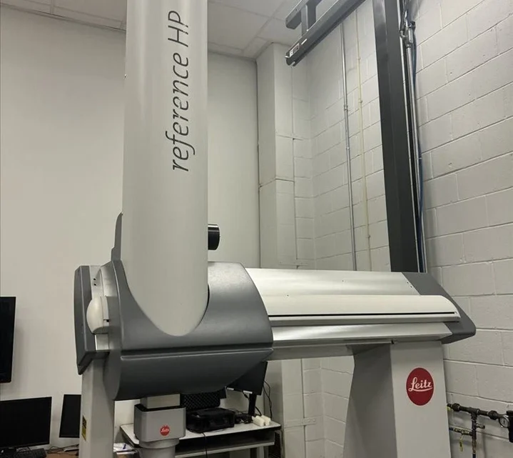
Before You Buy: Essential Criteria for Evaluating a Used, Second-Hand, Pre-Owned, Surplus Hexagon Leitz REFERENCE HP 30.9.7/B4S CMM Coordinate Measuring Machine made in Germany
Here’s a thorough, methodical checklist (with explanations and “red-flags”) for evaluating a used / surplus Hexagon / Leitz REFERENCE HP 30.9.7/B4S CMM (coordinate measuring machine). Because CMMs are precision metrology instruments, small degradations or misalignments can render them ineffective for high-accuracy work — so you’ll want to be very careful.
(“HP 30.9.7” refers to a large-volume “Reference HP” class CMM, typically with ~3000 × 900 × 700 mm measuring ranges or similar scaling in the Reference “12.9.7 / 30.12.9 / 30.9.7” families. For example, listings show “120 ” X, 36 ” Y, 28 ” Z” for a Reference HP 30.9.7/B4S.)
Below is a structured evaluation plan.
Why This Check Matters
The Leitz Reference HP series is designed for high-accuracy scanning / measurement in demanding metrology environments. According to Hexagon / Leitz literature, features often include:
- Granite base, dovetail guide plus air bearings or high-precision guides
- Bridge (portal) design with a triangular cross-section beam for stiffness
- Preloaded or precision guidance systems (air bearings, low friction)
- Compensation for thermal drift and environmental effects
- Compatibility with fixed scanning probe heads and sensor changes
- Modular sensor / probe change capability, real-time environment measurement (e.g. “PULSE”), thermal decoupling of motors and belts, etc.
Because of all that, any degradation in mechanical alignment, guide wear, electronics, sensor health or environmental control can degrade the “metrological chain” and introduce significant measurement errors or drift. The integrity of each subsystem matters.
Hence the evaluation must be both mechanical and metrological.
Pre-Visit / Preparatory Work
Before you physically inspect:
- Obtain the specification sheet / original drawings — nominal tolerances, measuring range (X, Y, Z), permissible accuracy (MPE), controller type (B4S in your model), sensor heads, software (e.g. Quindos / PC-DMIS or variant), probe rack, temperature compensation hardware.
- Ask for maintenance history / calibration logs — prior calibrations, rebuilds, guide replacement, sensor repair, upgrades.
- Request “machine powered” photos and videos — axes motion, probe head moves, “homing / referencing” sequence, coordinate readouts.
- Ask which sensor heads, stylus racks, probe change systems, rotary tables, fixtures are included — missing critical parts degrade usability.
- Arrange to bring or hire metrology / calibration equipment — such as a laser interferometer, calibrated spheres, gauge blocks, reference artifacts, etc.
- Verify environment & site conditions (floor vibration, temperature control, humidity) — CMMs are sensitive to environment.
Detailed Inspection & Testing Checklist
Below is a breakdown by subsystem with what to check, what’s acceptable, and red flags. Use it as a guide when you or your technical staff inspect.
| Subsystem / Area | What to Inspect / Test | Acceptable / Warning Levels | Why / Comments |
|---|---|---|---|
| Machine identity & configuration | Check nameplate, serial numbers, model designation (REFERENCE HP 30.9.7/B4S). Confirm control electronics are consistent with what was advertised. | Mismatches or untraceable modifications raise risk. | If internal modules have been swapped or if the controller is non-original, you may have compatibility or support issues. |
| Foundation, base, floor mounting, leveling | Inspect how the CMM was mounted: base plate, anchor points, leveling shims, possible foundation deformation, subsidence. | Any distortion, sagging, or misalignment from an improper foundation is a red flag. | A CMM must be well-founded, stable, and properly leveled; otherwise, measurement errors creep in. |
| Granite surface / table / surface plate | Check the granite table for chips, cracks, wear, flatness, surface markings. Use straightedge / optical flat / micrometer grid to assess local deviations. | Deviation beyond the machine’s tolerance (or too many small chips) is a problem. | The table is the reference upon which all measurements rest. Damage or wear will degrade precision. |
| Guideways / ways / axes motion system | Inspect the X, Y, and Z guide surfaces (rails, dovetails, guide blocks, air-bearing surfaces). Check for scratches, corrosion, wear, debris. Jog axes slowly to detect stiction, binding, rough motion. | Any binding, “notchy” movement, detectable roughness, or excessive play are serious issues. | In HP/Reference machines, guidance is often through high-precision guides or air bearings; wear or contamination can degrade performance severely. |
| Drive systems / belts / motors / pulleys | Check condition of belts (if used), alignment of belt paths, tension, pulleys, coupling, motor mounts. Jog axes back & forth, see any hysteresis, backlash. | Worn belts, misaligned belts, or coupling slack is problematic. | Smooth, low-vibration drive is essential for high-accuracy motion. |
| Encoders / scales / position feedback hardware | Inspect linear scales or encoders, cables, connectors, read-heads, sensor windows. Verify system can report position consistently when moved in small increments. | Errors, dropout, noise, misalignment, or irregular signals are red flags. | The position-feedback is critical to closing the metrology loop. Faulty encoders cause measurement error. |
| Temperature / environmental sensors & compensation hardware | Check that sensors (thermometers, compensation probes) are present and functioning. Check any ambient / chamber sensors, or PULSE environmental logs. | If sensors are missing, nonresponsive, or degraded, the CMM cannot properly compensate for thermal drift. | Thermal compensation is a core part of high-precision CMM operation. |
| Bridge / cross-rail / gantry stiffness & alignment | Check for any bending, sag, wear, or repairs in the cross-bridge, beam, and supports. Use a reference bar or straightedge to test for twist or deflection. | Excessive deflection, twist, or prior weld repairs are warning signs. | The bridge geometry must remain rigid and stable under motion and load. |
| Z-ram, vertical axis (Z) system | Check vertical motion smoothness, balance, counterbalance (if present), any drift, binding. Inspect leadscrew, nut, air bearings (if used), or vertical guidance surfaces. | Drift or binding is unacceptable; any noticeable jerk or stick-slip is bad. | The Z axis often carries the probe head and its load; any error here multiplies measurement error. |
| Probe head(s), sensor(s), stylus / stylus racks / probe changer | Inspect probe head(s) for runout, calibration drift, repeatability. Check stylus rack / probe changer mechanisms (if included). Check that the probe head indexing (if applicable) is accurate. | If the probe head cannot return to known positions with high repeatability, or if the stylus changer is faulty or stuck, the CMM is less usable. | The probe is the “measuring tip” of the system — any error or instability here directly affects measurement results. |
| Software, controller, electronics, interface | Power up the controller (B4S in your machine). Check that the UI / console works. Jog axes, run homing / referencing sequence. Inspect electronics cabinets, wiring, connectors, look for signs of burned components, loose boards, aging capacitors. | Frequent error codes, unstable behavior, communication glitches, or missing modules are red flags. | Because much of the measurement pipeline is software-based, controller integrity is critical. |
| Accuracy test / calibration artifact checks | Use calibrated reference spheres, gauge blocks, step artifacts, or interferometric equipment to test volumetric error, straightness, retrace error. Run standard calibration / compensation routines. | If deviation exceeds acceptable MPE (e.g. as originally specified) or shows significant drift, the machine may need full re-flow / re-calibration. | This is the “proof in the pudding” — mechanical checks are necessary, but only metrological testing confirms measurement capability. |
| Repeatability / probing repeatability | Execute repeated probing of the same point with minimal repositioning, under various directions, and measure spread (scatter). | If repeatability error is larger than the machine’s spec or your required tolerance, it’s a weakness. | Good repeatability is critical for consistent, reliable measurement. |
| Thermal stability / drift over time | Run the CMM over a warm-up period (e.g. 1 hour) under ambient conditions. Monitor drift in measured positions of reference artifacts. | If drift exceeds your tolerance (e.g. several microns), or is nonuniform / unpredictable, it’s problematic. | CMMs are sensitive to thermal expansion; drift must be small and compensable. |
| Vibration, floor interference, external disturbance | Observe for vibration from nearby machinery, HVAC systems, foot traffic. Try measuring with and without intentional external disturbance to see sensitivity. | If the machine is excessively sensitive to external vibration, its usable accuracy is compromised. | A precision metrology machine must reside in a stable, low-disturbance environment. |
| Utility / support systems (air supply, cooling, power, grounding) | Inspect compressed air supply (if used for air bearings), cleanliness and pressure regulation. Verify that cooling / temperature control systems are functional. Inspect electrical supply, grounding, stable voltage. | Air pressure fluctuations, leaks, poor grounding, unstable power are red flags. | Air bearings and environmental stability are part of the precise functioning of high-end CMMs. |
| Safety, guards, covers, cable management | Ensure all protective covers, cable drag chains, safety interlocks, collision protection systems are present and functioning. | Missing or damaged covers or safety systems are undesirable and may require retrofit. | Safety and protection of the machine and probes are essential for long-term reliability. |
| Calibration certificates, reference ball set, documentation | Request and inspect calibration certificates, reference sphere logs, historic compensation & calibration data, operator’s / maintenance manuals, wiring and mechanical drawings. | Missing or questionable documentation reduces confidence. | Documentation is critical for servicing, recalibration, and traceability. |
| Spare parts, supportability, upgrade path | Ask whether critical spares (electronics boards, motor drivers, encoder heads, sensor heads) are still available. Ask whether upgrades or retrofits (e.g. new controllers, sensors) are feasible. | If many parts are obsolete or unobtainable, long-term viability is low. | A CMM is only as good as your ability to maintain and calibrate over its life. |
Tolerances, Benchmarks & What You Should Expect
Because each CMM is different and because your intended measurement tasks define acceptable tolerances, I’ll give some benchmark ranges (these are illustrative, not universal guarantees). Use them as “red-flag thresholds” rather than strict pass/fail criteria.
| Parameter | Good / Target Range | Caution / Warning Range | Comments |
|---|---|---|---|
| Volumetric accuracy / MPE (as-built) | A few microns over typical volume (e.g. 3–6 µm or better) | > 10 µm over full volume may be too large for precision tasks | Compare to manufacturer’s original spec (if available) |
| Probing repeatability | Sub-micron to low µm (e.g. 0.5 µm to 2 µm) | > 3–5 µm scatter is questionable for tight tolerance work | Depends heavily on probe / stylus setup |
| Straightness / linear error | Below a few microns over nominal axes travel | Deviation in the tens of microns is too large | Evaluate over segments of travel as well |
| Backlash / “lost motion” | Very tight, ideally undetectable or within a few µm | Noticeable backlash or hysteresis is a red flag | Though many CMMs use zero-lash systems, any play is negative |
| Drift over time (thermal) | < few microns over an hour (depending on environmental stability) | Drift > 5–10 µm or unpredictable drift | Acceptable drift depends on part tolerance |
| Sensor / probe head repeatability, wear | Minimal degradation from new, stable over time | Excessive tilt, index error, or wear in head mechanisms is bad | Probe head is often the hard-to-repair link |
| Encoder / scale error / repeatability | Very low error, high consistency over direction changes | Dropouts, non-linearity, noise cause measurement uncertainty | Feedback stability is critical |
Deal-Breakers & Red Flags
While many flaws can be discounted or estimated in price, some are serious enough to strongly avoid or demand high discounts:
- Cracks, structural damage, or repairs in the bridge, base, or supports
- Severe wear or damage to granite surface / table
- Binding, rough motion, or non-smooth axes behavior
- Faulty or degraded encoders / scale read heads
- Broken or nonfunctional probe heads, stylus changer, or sensor modules
- Electronic / controller instability, frequent errors, missing modules
- Large calibration errors or inability to bring the machine into spec
- Unrecoverable thermal drift or unstable environmental sensitivity
- Absence of calibration / audit trail / documentation
- No availability of critical spare parts (scale heads, electronics, probe module)
- Poor or unknown maintenance history
- If the asking price + refurbishment / recalibration cost approaches or exceeds a newer or better-maintained alternative
Practical Tips & Strategy
- Bring (or hire) a metrology / CMM expert with calibration tools and experience.
- Insist on a “brown-field” measurement test of your own reference artifacts (e.g. spheres, gauge blocks) during inspection.
- Run the machine for some time (warm-up, steady-state) and track drift, noise, thermal behavior.
- Ask for “as-found” vs “as-left calibration data” to see how much compensating adjustments were applied.
- Negotiate conditional acceptance (if drift or error is above X, seller must re-calibrate or discount).
- Ask for spare parts or spares stock to be included — probe heads, scale sensors, controller modules.
- Evaluate retrofit / upgrade possibilities — perhaps upgrading controller or sensor heads might bring the machine’s performance back to spec at lower cost than full replacement.
- Check compatibility with your software stack (e.g. Quindos, PC-DMIS, or whichever you use).
- Plan for environmental control — temperature stability, humidity, vibration isolation, air supply (if required).
- Budget for recalibration and alignment once relocated. Even a “good” used CMM will need recalibration and alignment in your facility.