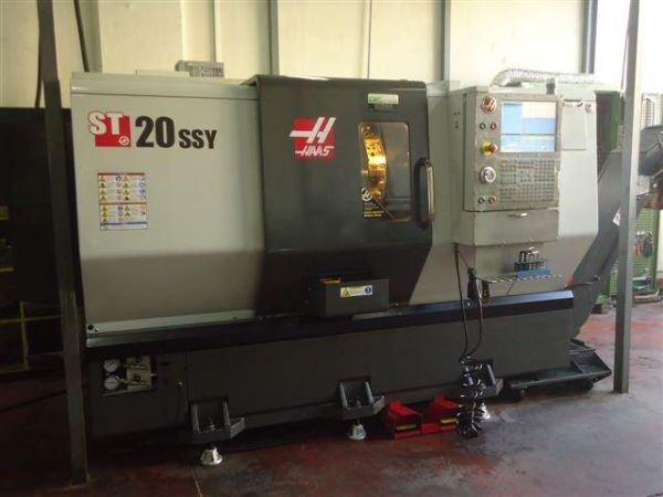
Before You Buy: Essential Criteria for Evaluating a Used, Second-Hand, Pre-Owned, Surplus HAAS ST 20 SSY CNC Turning Center C-Axis Live Tooling Y-Axis made in USA
If you are considering buying a HAAS ST-20 SSY (or ST-20 SSY / ST-20 Y / Live Tooling / C-Axis) CNC turning center (made in USA) as a used / surplus machine, here is a carefully tailored checklist of what to inspect, test, and document to protect your interests and avoid surprises. Much of this is common to complex CNC lathes, but I’ll emphasize what’s particularly critical in a live-tool, C-axis, Y-axis turned machine.
Before diving into the checklist, some reference specs and features you should verify (based on HAAS’s published material):
- The ST-20Y / ST-20 SSY series supports ±51 mm Y travel (i.e. a total of ~102 mm) for off-center milling, drilling, and tapping.
- The ST-20 SSY often includes live tooling + C-axis capability as standard.
- Standard spindle speed is 4,000 rpm; optionally higher speeds (5,000 rpm) for “SSY” models or live tooling.
- Motor power (spindle vector drive) up to ~22.4 kW (or ~30 Hp in some versions) in SSY / high-speed configs.
- Chuck size: 210 mm (≈ 8.3″) and bar capacity ~ 63.5 mm (2.5″) in the Y-axis versions.
- Turret: For the SSY version, a 24-station BOT / VDI hybrid turret is commonly used.
- The machine ships with significant weight and size (crating and shipping specs).
These specs help you set expectations and also give you baseline figures to test against.
1. Visual & Structural Inspection
- Frame, base & casting integrity
Check for cracks, weld repairs, corrosion, or distortions in the bed, base, casting supports. Any deformation or previous repair may affect precision. - Column, turret housing, supports
Inspect the turret housing, supports, and cross structures. Look for wear, misalignment, or damages from collisions. - Enclosures, covers & guards
Ensure all covers, splash guards, chip shields, doors are present and functioning. Missing guards or broken doors are a red flag. - Chip / coolant accumulation
Check whether there is excessive buildup of chips, sticky residue or corrosion. Poor housekeeping often signals neglect.
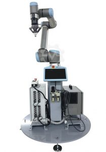
2. Spindle, Live Tooling, C-Axis & Y-Axis Mechanisms
Since this machine supports live tooling + Y + C axis, these subsystems are among the most vulnerable and expensive to repair.
- Spindle & bearings
Rotate spindle manually (if safe) to feel for smoothness. Run at low rpm and listen for noise, hum, or vibration. Use an indicator to measure runout at the nose and at extended tooling. Check bearing play. - Live tooling spindles
Test that live tooling spindles spin freely and without excessive vibration or noise. Check for consistent speed, torque behavior, and that higher-speed live tooling capabilities are functional (if included). - C-axis
Check C-axis indexing, torque, and backlash. The C-axis should rotate precisely and lock without play. Measure angular positioning accuracy. - Y-axis
Check Y-axis movement both positive and negative directions. Look for binding, backlash or uneven motion. Measure straightness and repeatability of Y-axis motion under load. - Tool cables, wiring, and lines
Because live tooling and Y / C axes typically require additional cabling (for coolant, power, signal), check for cable fatigue, insulation damage, wear, proper shielding, slack loops, and strain relief.
3. Turret, Tool Holding & Tool Changing
- Turret mechanism & indexing
Cycle turret through all tool stations multiple times. Observe indexing speed, smoothness, alignment, and whether any jamming or mis-indexing occurs. - Tool holders, adapters & clamping
Inspect toolholder shanks, locating surfaces, collet holders, or drive adapters for wear, damage, or distortion. - Back-to-back tool changes & stability
Check repeated tool change cycles for consistency. Watch for any mis-insertion, drift, or indexing errors. - Torque and mechanical rigidity at live tooling positions
At the extremes of the turret (live-tool positions) assess whether rigidity is maintained under light loads (e.g. small milling or drilling).
4. Slideways, Guides & Axis Motion (X, Z, Y)
- Axis motion & smoothness
Move axes (X, Z, Y) at various speeds and positions. Check for sticking, jerkiness, dead zones, or erratic behavior. - Backlash & play
Use a dial indicator or laser test to detect backlash or free play in each axis and its drive nut or mechanism. - Guideway condition
Inspect the ways (linear guides, box ways, hardened surfaces, etc.). Look for pitting, corrosion, evidence of chatter, wear lines, or mismatch in wear. - Gibs, preloads, wipers
Check whether gibs are adjusted properly, and whether wipers/seals are intact. Missing or damaged wipers accelerate wear.
5. Electrical & Control Systems
- Control unit & software
Power on the CNC, check boot behavior, error logs, alarms, memory, program storage, backup capability, and software version integrity. - Drive amplifiers, servo motors, inverters
Inspect drives & control cabinets for burn marks, cleanliness, intact wiring, good cooling, and ventilation. Check for failed or replaced modules. - Interlocks, E-stop, limit switches
Test all safety circuits, interlocks, emergency stops, door interlocks, proximity switches, limit/home switches for proper operation. - Wiring harnesses & connectors
Check wiring for brittle insulation, chafing, looseness, strain reliefs, and overall neatness. Live tooling and Y / C axes increase wiring complexity, so poor cable management is a red flag. - Power compatibility
Verify voltage, phase, current requirements match your facility or that an adaptation plan is feasible.
6. Lubrication, Cooling & Auxiliary Systems
- Way & axis lubrication
Check lubrication pump, lines, filters, flow to each axis and critical bearing. Ensure delivery to live-tool heads, Y / C axes is intact. - Coolant system
Test coolant pump, plumbing, nozzles, filtration, flow control, check for leaks or corrosion. For live tooling, ensure coolant reaches those tool positions. - Chip evacuation / chip conveyor
Verify chip conveyor (if equipped) works smoothly, no jams, paddles intact, debris removal effective. - Seal integrity & guarding
Check seals, splash guards, and that coolant/chip ingress to electrical areas is prevented.
7. Geometric Accuracy & Calibration
- Run test cuts
Under light machining, cut test parts and measure for tolerances, surface finish, roundness, cylindricity, and straightness. - Volumetric / multi-axis compensation
If the control has compensation capabilities (for Y, C, etc.), test whether volumetric compensation or calibration was maintained. - Thermal drift / stability
Run the machine under load for an extended period and monitor whether positioning errors change over time due to temperature. - Alignment tests
Check squareness of axes, perpendicularity, and alignment of live-tool axes relative to main turning axes.
8. Maintenance & History
- Service records & logs
Ask for maintenance logs, service reports, replacement history (bearings, motors, wiring), usage patterns (hours, load profiles). - Repair or collision history
Inquire whether the machine had crashes, hits, or rebuilds, especially of the turret, live-tool axes, or spindle. - Documentation, parts & support
Confirm whether manuals, electrical/circuit diagrams, parts lists, software backups, and original documentation are available. Also check whether spare parts (especially live tooling, turret parts, Y / C axis components) are still available.
9. Trial / Demonstration & Burn-in Testing
- No-load motion test
Before cutting, run axis moves, tool changes, spindle rotation, Y / C axes, live tooling, clamping/unclamping sequences, and let the machine run idle to observe stability. - Loaded test cuts
Perform representative machining operations (turning + milling / drilling) to validate full functional capability, and check surface finish, tolerances, vibration, deflection. - Soak / extended run test
Run the machine for longer durations to observe temperature shifts, drift, error accumulation, intermittent faults, or degradation under time. - Full option exercise
Use combinations of features (e.g. live tooling + Y + C + tool changes + direction reversals) to stress the system in real-world use.
10. Measurement & Benchmarking
- Record data
Capture spindle runout, axis backlash, vibration amplitude, positioning deviations, thermal drift, repeatability in Y, C, and turning axes. - Compare with tolerance needs
Check whether measured deviations fall within the tolerances you need for your parts. If not, budget for rework or alignments. - Photograph & document
Take photos of wear, damaged areas, cable runs, marks, and measurement setups for reference and contract proof.
11. Safety & Compliance
- Guarding & interlocks
Ensure all moving parts, live tooling spindles, rotating turrets, etc. have proper guards and interlock circuits. - Operator access zones & safe design
Ensure the working envelope, doors, and operator interface are safe and that accidental contact with moving parts is prevented. - Electrical safety & grounding
Check proper grounding, insulation, electrical panel enclosures, and compliance with local safety regulations or CE / OSHA where applicable.
12. Installation, Transport & Site Preparation
- Machine size & weight
Check shipping weight and dimensions (with crating) — for SSY versions these can be quite heavy and large. - Rigging & moving plan
Determine lifting points, disassembly needs, transport, and reassembly cost. Ensure your facility has adequate crane / forklift capacity. - Foundation, leveling, damping
Plan for foundation, anchoring or vibration damping, high-precision leveling, and alignment on your shop floor. - Utility requirements
Ensure your facility matches power, cooling, air, coolant, drainage, and ventilation needs of the machine.
13. Warranty / Acceptance Terms & Risk Mitigation
- Test / acceptance period
Negotiate a burn-in period (e.g. 30-90 days) to run full cycles and validate the machine’s performance under your load. - Conditional payment / holdback
Tie some part of payment to passing key test criteria or acceptance of performance. - Seller disclaimers & guarantees
Ask for seller’s acknowledgment of known defects, and ideally a limited warranty on critical subsystems (spindle, live-tooling, Y / C axes). - As-is & return rights
Try to insert terms that allow return or repair if critical failures appear within the acceptance period.
14. Pricing & Risk Reserves
- Estimate refurb cost
Based on observed wear, need for alignment, bearing replacement, control refurbishment, calibrations, etc., estimate your repair / reconditioning cost. - Set a reserve margin
Leave buffer (e.g. 10–20 % or more) in your offer to account for unforeseen repairs or part shortages. - Use data for negotiation
Use measurement results, observed wear, missing options, or functional deficiencies as negotiation leverage.