15/10/2025
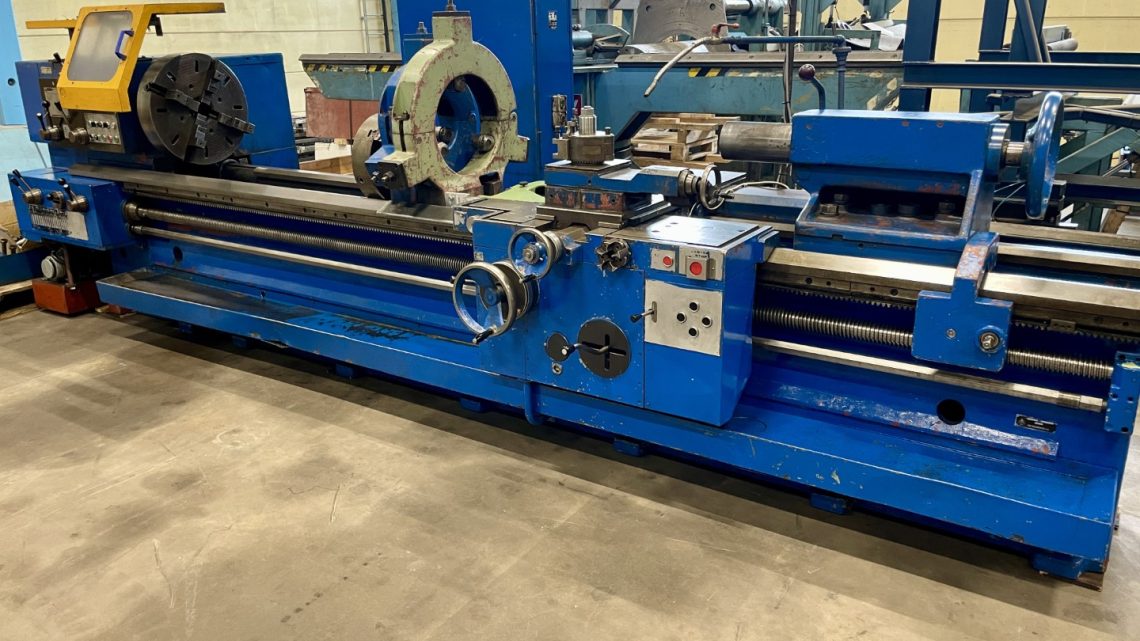
Before You Buy: Essential Criteria for Evaluating a Used, Second-Hand, Pre-Owned, Surplus TOS SUS63x3500 Universal Lathe made in Czech Republic
Below is a comprehensive buyer’s due-diligence checklist tailored for evaluating a used / surplus TOS SUS63×3500 universal (or “support / engine”) lathe (Czechoslovakia / Czech origin, by TOS). Use this to verify condition, spot red flags, estimate refurbishment cost, and negotiate with confidence.
some reference data for the SUS63×3500 to anchor expectations:
- Swing over crosslide: ~ 390 mm
- Center (turning) distance: 3,500 mm
- Spindle speed range: approx. 7 – 1,120 rpm
- Motor: ~25 kW drive
- Weight / dimensions: length ~ 6,400 mm, width ~1,750 mm, height ~1,500 mm, weight ~7,100 kg
Those are reference values; the actual machine you inspect may differ (e.g. modifications, wear, retrofits). Use the checklist below and record actual measurements.
Inspection & Testing Checklist for TOS SUS63×3500 Universal Lathe
| Area | What to Inspect / Test | Why It Matters & Risk | Suggested Checks / Targets / Notes |
|---|---|---|---|
| 1. Identity, Nameplates, and Spec Confirmation | • Check nameplates, builder plates, serial numbers, and stamped data (swing, bed length, maker, year). • Confirm that the model is indeed SUS63×3500 or variant. • Verify any control retrofits, modifications, or non-original parts. | Ensures you know exactly what you’re buying, helps in sourcing spares and comparing to expected spec. | The machine should match a “63 / 3500” designation (i.e. ≤ 630 mm over bed, 3,500 mm swing). |
| 2. Frame, Bed, & Base Structure | • Inspect the bed, bedways, guides, gap in gap-bed (if gap version) for wear, corrosion, chatter marks. • Look for cracks, repairs, welds, distortions in the bed, base, mounting brackets. • Check alignment/twist in the base. • Assess lubrication channels, drains, cast iron integrity. | The structural foundation dictates accuracy, rigidity, and lifetime. Repairing a warped bed is very expensive. | The bed should be straight, flat within tolerance for your workbearing requirements. No obvious repairs or misalignment. |
| 3. Headstock & Spindle | • Rotate the spindle manually (if safe) and feel for smoothness, binding, or rough spots. • Run test spindle at low speed; listen for abnormal noise, hum, vibration. • Measure spindle runout (with a precision bar or dial indicator) at the nose and outboard • Check bearing condition (temperature, play) • Inspect spindle nose and taper for wear, nicks, and cleanliness • Inspect internal gear / drive train (if geared) for backlash, wear | The spindle is among the most expensive and critical components; bearing failure, wear, or damage severely degrade performance. | Acceptable runout should be within few microns (≤ 0.01 mm or better, depending on your tolerances). No excessive play in bearings. |
| 4. Gears, Feed Drives & Transmission | • If the machine uses gears or gearboxes for spindle speed changes or feed changes, shift through all speeds and observe behavior. • Listen for gear whine, clashing, backlash, lugging. • Check condition of gear teeth (pitting, wear), lubrication of gearboxes. • Test longitudinal and cross slide drive mechanisms (leadscrews, nuts, gear trains). • Check for backlash in feed screws and nut wear. | Worn gears or drive trains can result in inaccuracy, vibration, inability to maintain consistent speeds/feeds. Gearbox repair is costly. | Smooth transitions, minimal backlash, no abnormal noise, no binding. |
| 5. Cross Slide / Carriage / Tool Slide Condition | • Check travel in longitudinal (Z) and cross (X) axes; observe for binding, roughness, or hesitation. • Use dial indicators / test bars to measure straightness and flatness across travel. • Check surface finish of guide ways, condition of way wipers, lubrication components, wear marks. • Measure backlash or play in the slides, nuts, or gibs. • Verify “rapid traverse” if present. | Poor slide condition leads to inaccuracy, chatter, inability to maintain tolerances. | Slide motion should be smooth, no stiction, minimal backlash (within your tolerance). Wipers and lubrication should be intact. |
| 6. Tailstock & Alignment | • Check the tailstock spindle / quill: smooth travel, no binding, minimal play. • Inspect quill taper, diameter, condition. • Verify alignment of tailstock along the bed: test by setting indicator on a known bar and moving carriage. • Check tailstock locking mechanisms and clamping. | Tailstock misalignment or worn quill can cause taper, runout, or poor support of longer workpieces. | Tailstock offset should be minimal relative to your part tolerances (often ≤ a few hundredths of a mm over full length). |
| 7. Chuck, Jaws, Clamping & Workholding | • Inspect chucks (3-jaw, 4-jaw) and their jaws for wear, damage, proper grip. • Check mounting, keyway, fastening surfaces. • If the machine has special workholding (steady rests, follow rests), inspect their condition and alignment. • Test clamping / unclamping operations. | Poor workholding degrades accuracy, causes slippage, or damage to workpieces. | Chucks should grip firmly and uniformly. Jaws should be true, not overly worn or damaged. |
| 8. Controls, Electrical Systems & Wiring | • Open control panels and inspect wiring, connectors, terminal blocks, relays, fuses, circuit breakers for signs of overheating, corrosion, melted insulation, or repairs. • Test all switches, buttons, emergency stops, indicator lights. • Confirm power compatibility (voltage, phase, current) with your facility. • If there is a digital readout (DRO) or CNC control retrofit, verify its functionality, accuracy, and interface (inputs/outputs, memory, backup). • Look for custom wiring or modifications that deviate from standard configuration. | Electrical faults often cause machine downtime or catastrophic failures. Having a clean, reliable wiring/control system is essential. | All electrical panels must be clean, well-maintained. No burnt components, wires, or loose connections. Controls should function as intended. |
| 9. Lubrication, Coolant & Auxiliary Systems | • Check the lubrication system: oil pump, lines, filters, reservoirs, flow to ways and slides. • Inspect coolant systems (pump, plumbing, nozzles, filters) if the lathe is equipped. • Look for leaks (oil, coolant) or past repairs in plumbing. • Inspect chip guard, chip removal system (splash guards, scrapers, coolant return paths) • Check seals, gaskets, wipers, and that the machine is sealed to prevent ingress of chips or coolant into sensitive parts. | Good lubrication and coolant are necessary to maintain tolerances and reduce wear. Poor auxiliary systems accelerate degradation. | Lubrication lines should deliver oil, lines should be clean. No significant leaks. Coolant flow should be adequate and controllable. |
| 10. Safety, Guards & Interlocks | • Ensure all guards, splash shields, covers, and protective enclosures are present and in place. • Test emergency stops, limit switches, door or access interlocks. • Check the robustness of guard design (i.e. they should withstand impact or deflection). • Confirm proper grounding of electrical components. • Verify any signage, safety labels, and that operator control zones are safe. | Safety compliance is essential for legal use, operator protection, and liability. Missing or bypassed interlocks are serious red flags. | All safety devices should be functional. No bypassed switches or open panels while running. |
| 11. Test Runs & Performance Evaluation | • Run the lathe (if power available) with no load first — jog motions, axis moves, spindle run. • Then perform test cuts (turning, facing) on a suitable workpiece (steel or your typical material). Examine finish, geometric errors, drift. • Run extended (soak) test to detect heat drift, vibration changes, shifts, or emergent faults. • Cycle through full speed, feed ranges, direction changes, axis reversals, and long travel moves. • Monitor temperature of bearings, motors, gearbox, and observe vibration or noise changes over time. • If possible, perform an alignment / calibration test (e.g. check taper, cylindricity, straightness over the full length). | This is your “proof in action” — many defects reveal themselves only under actual operation or time. | The machine should operate smoothly, maintain consistent finish, not overheat, and not produce faults or drift beyond acceptable tolerances. |
| 12. Measurement & Benchmark Data Collection | • Using indicators, sensors, or measurement tools, record: spindle runout, vibration amplitude, backlash in slides, positional deviation over travel, thermal drift over time. • Compare your measured data with your required tolerances (for your parts) and with reference spec (if known). • Take photos of wear areas, measurements, alignment test data. | Data is your evidence for negotiating, acceptance, or rejecting the machine. It helps quantify the condition. | The measured values should fall within your tolerance envelope for production. If they are outside, you must assess repair cost. |
| 13. Maintenance History, Documentation & Spares | • Request any maintenance logs, repair records, overhaul history, parts replacement logs. • Ask if any major repairs or accidents (crashes) occurred. • Confirm presence of original or as-built documentation: wiring diagrams, parts list, mechanical drawings, service manuals. • Check availability of spare parts (bearings, slides, gears, chucks, ways, etc.) for this model. • Ask about whether TOS or aftermarket support is available in your region. | Even a good machine can become unusable if you can’t source parts or knowledge. Documentation increases your ability to service it. | Comprehensive documentation and spares availability. |
| 14. Transport, Installation & Site Requirements | • Determine the machine’s weight, footprint, and center of gravity to plan rigging and floor support. • Check that your facility’s floor can support ~7,000 kg (or actual weight of this unit). • Plan for costs of disassembly, rigging, re-leveling, alignment, and recommissioning. • Confirm access paths (doors, cranes, lifts) to move the machine into place. • Check power supply (voltage, phase, capacity), grounding, compressed air (if used), coolant supply, drainage, and ventilation. | Hidden costs in moving, installing, and aligning can be significant. Poor site preparation can compromise machine performance. | Ensure your shop infrastructure is adequate. Rigging plan should be safe and feasible. |
| 15. Warranty / Acceptance Terms & Risk Mitigation | • Try to negotiate a short test / acceptance period (e.g. 30-90 days) during which you can run and validate performance. • Tie final payment to successful performance against key criteria (accuracy, finish, reliability) • Insist that the seller disclose known defects, and possibly provide a limited warranty on critical subsystems (spindle, gears) • Ask for spare parts (if available) to be included or priced separately • Document condition with photos, test results, before final acceptance | Because used machines carry risk, you need contractual safeguards and leverage to protect yourself. | A successful acceptance clause helps reduce your exposure to hidden defects discovered later. |
| 16. Pricing Adjustment & Repair Reserve | • After inspection and measurement, estimate the cost of repairs, replacements (bearings, slide repair, alignment, retrofits) • Leave a margin in your offer to absorb surprises • Use defects or measurement deviations as leverage to lower price or request seller to address issues • Don’t pay as if the machine is “good as new” — incorporate refurbishment cost into your bid | Even well-maintained machines often require “tune-up” work before reliable production. You should not be caught paying for unknown costs. | A prudent reserve (often 10–25 % of purchase price) should be assumed for commissioning / repairs. |