15/10/2025
Before You Buy: Essential Criteria for Evaluating a Used, Second-Hand, Pre-Owned, Surplus BREDA RB 55 / 2000 Radial Arm Drilling Machine made in Italy
Here’s a tailored due-diligence checklist (with commentary) for evaluating a used BREDA RB 55 / 2000 (or R 55-2000) radial arm drilling machine (Italian origin) before purchase. Use this as your buyer’s protection tool.
Based on listings, here is a sample spec baseline to anchor your inspection:
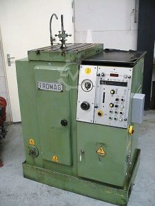
- Manufacturer: G. BREDA, Italy (machine origin confirmed as Italy)
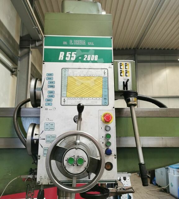
- Model: R 55-2000
- Drilling capacity in steel approx. Ø 55 mm
- Spindle drive: 5.5 kW, 400 V (for at least one listing)
- Spindle speeds: 30 – 1,200 rpm (12 speed steps)
- Arm reach: 320 / 2005 mm (min / max)
- Weight: ~4,800 kg
- Other features: MK5 spindle taper, 8 feeds from 0.06 – 1.00 mm/rev, coolant, central clamping, cube table, hydraulic vice
You should treat those as reference values; your specific unit might deviate or have different options.
Key Evaluation Criteria for Used Radial Arm Drilling Machines
Below is a structured checklist of what to inspect, test, verify, and document. Wherever possible, obtain measurements or evidence, not only visual inspection.
| Area | What to Check / Test | Why It Matters / Potential Risks | Acceptable / Target Values (if known) |
|---|---|---|---|
| 1. Structural & Mechanical Integrity | • Inspect base, column, arm, boom, castings for cracks, weld repairs, distortions, corrosion, or repairs. • Check condition of slideways, guides, and ways on arm and headstock travel. • Inspect any bracing, ribbing, or stiffeners for damage. • Check that all covers, guards, shields are present and intact. | Damage, warps or cracks will reduce alignment, rigidity, and lifetime; re-machining or repair is expensive. | No visible cracks, weld patches, or distortion. Guides should be straight and unbowed. |
| 2. Boom / Arm Travel & Mechanics | • Check the boom/arm vertical movement (raising/lowering) over full stroke. • Inspect supporting mechanisms (hydraulic, screws, counterbalance). • Verify that arm radial traverse (i.e. boom sliding) is smooth, no binding. • Inspect lubrication to these moving parts. | If the arm or boom is stiff, worn, misaligned, or binding, drilling will suffer, and repairs are costly. | Smooth motion over full travel; no “dead spots” or jolts. |
| 3. Spindle & Quill | • Rotate spindle (manually or in low power) to feel for smoothness, binding or roughness. • Check internal spindle bearings via noise, vibration, temperature (during light run). • Measure runout of the spindle nose using a dial indicator (with test bar). • Examine drawbar or retention mechanism if present. • Inspect quill / feed mechanism (if the head moves radially or axially) for play, binding, backlash. • Check quill stroke length, integrity of feed screws, and way surfaces. | Spindle or quill issues (e.g. bearing wear, axial play, excessive runout) severely degrade drilling accuracy and may require costly overhaul. | Runout: ideally within a few microns (≤0.01 mm or better). Quill stroke should match spec (e.g. 240 mm in one listing) |
| 4. Travel / Positioning / Accuracy | • Use indicators to check alignment, straightness, and geometry over the full swing. • Check radial accuracy across arm reach, vertical alignment, perpendicularity to base, etc. • Measure backlash or play in any movement axes (arm, headstock, quill, etc.). • Run a test drill or spot in known test bar or alignment template to validate positional accuracy under load. | Even if mechanical parts are intact, poor alignment or geometry will produce out-of-spec holes, taper, drift, or mislocation. | Backlash should be minimal (≤ few microns). Positional deviation should be within your tolerance needs (e.g. ±0.05 mm or better, depending on your use). |
| 5. Spindle Speeds, Feeds & Drive Train | • Verify the gearbox or spindle drive gear train (if stepped) shifts correctly across speeds. • Verify feed mechanism (if variable or stepped) works across the full feed range. • Run the spindle through all speed steps and observe vibrations, noise, smoothness. • Check belts, couplings, gears for wear or damage. | Any issues here reduce flexibility, cause vibration, reduce drilling quality, or risk drive failure. | All speed steps operate cleanly. Feeds shift without jerk or skipping. |
| 6. Clamping, Holding & Workpiece Fixturing | • Inspect the base plate / table (size, T-slots, flatness, condition). • Check any hydraulic / pneumatic clamping systems, central clamping, vices, cube tables. • Verify that the spindle-to-base distance range is achievable and consistent. • Check for clamp alignment, repeatability. | Poor clamping or fixturing leads to workpiece movement, inaccuracies, dangerous failures. | Clamps engage reliably, no drift. Table is flat and true to the reference surfaces. |
| 7. Motor, Electrical & Control Systems | • Inspect the electrical cabinet, wiring, motor drives, switchgear, fuses, relays. • Check motor condition (windings, vibration, noise). • Ensure proper power compatibility (voltage, phase, current) with your facility. • Check control panel(s) (if digital/digit readout), switches, buttons, indicators. • If there is a digital readout (DRO) or control system, confirm it functions and is accurate. | Even mechanical perfection is useless if the electrical or control systems fail. Rewiring or control replacements are expensive. | All motors run without overheating or fault codes. Controls respond reliably. |
| 8. Lubrication, Coolant & Auxiliary Systems | • Inspect the lubrication system (oil lines, pumps, reservoirs)—are they functional and not clogged? • Check coolant pump, lines, valves, filtration, and distribution to the spindle if coolant is provided. • Check for leaks: oil, coolant, hydraulic fluid. • Inspect filtration, strainers, pipes for rust, scaling, corrosion. | Without good lubrication, wear accelerates rapidly. A failed coolant system severely limits deep drilling or throughput. | Lubrication system should supply oil uniformly. No leaks. Coolant flow adequate for full drills. |
| 9. Safety, Guards & Interlocks | • Ensure all guards, shields, covers, chip guards, etc., are present and not overly damaged. • Test emergency stops, limit switches, interlocks. • Verify safety of electrical panels (covers, grounding, insulation). • Check compliance (if required) with local safety / machine directives. | Safety lapses pose liability hazards; missing or nonfunctional interlocks are red flags. | All safety devices should function properly; no bypassed interlocks. |
| 10. Maintenance History, Documentation & Spares | • Request maintenance logs, repair history, usage hours or load cycles. • Ask about any known crashes, repair work, or major refurbishments. • Check if original manuals, circuit diagrams, parts lists, technical drawings are present. • Inquire on spare parts availability (bearings, spindle parts, gearboxes, clamps, motors). | Even a machine in good shape can become a liability if parts or knowledge are unavailable. | Complete documentation, spare parts access, known history. |
| 11. Transport, Installation & Site Considerations | • Determine size, weight, center of gravity, lifting points, disassembly needs. • Check floor load capacity and foundation requirements. • Estimate rigging, re-leveling, alignment cost at your site. • Check access (doorways, overhead crane, floor space). | You don’t want hidden cost surprises from moving, reinstalling, or leveling the machine. | Transport and installation feasible within your budget. |
| 12. Trial Run & Load Test | • If possible, run the machine under light drilling load (test material) through a complete cycle; inspect hole quality, straightness, runout. • Run extended operation (soak test) to monitor stability, temperature drift, vibration, any abnormal behavior. • Step through speeds, feeds, reversals, and full range cycles. | This is your final “proof of life” test; hidden issues often manifest only under load or after some time. | No alarming noises, sudden faults, drift, or instability. Acceptable surface finish and dimensional accuracy in test cuts. |
| 13. Measurement & Benchmark Data Acquisition | • Document key measurements: runout, backlash, positional deviation, thermal drift, vibration amplitude. • Compare these with your tolerance needs or the original spec baseline. • Use those data as negotiating leverage. | Measurements are evidence; without them you are negotiating blind. | Values should be within your acceptable error budget (for your parts). |
| 14. Price Adjustment / Risk Contingency | • Based on the measured condition, estimate repair / refurbishment costs (bearings, guides, control, spindle, alignment). • Negotiate an allowance or price reduction for known defects. • Try to include a testing / acceptance period or conditional payment tied to demonstrated performance. | Good due diligence + negotiated risk buffer is how you protect yourself as a buyer. | Ensure you have margin to absorb repairs or surprises. |
Specific Considerations for the BREDA R 55-2000
Given the model, here are additional points to pay particular attention to:
- The radial reach (arm length) is substantial (min 320 mm to max ~2005 mm) — at long reach, deflection and stiffness become critical; ensure arm deflection under load is acceptable.
- The column diameter (e.g. 360 mm in one listing) and boom flex are structural limits to watch.
- The vertical adjustment / boom stroke (listed ~855 mm in one spec) should be examined for smoothness and rigidity.
- The spindle’s 12-speed gearbox (30–1200 rpm) and feed gearbox (8 feed rates, 0.06–1.00 mm/rev) should all shift cleanly.
- Clamping area of base / table is approx. 1000-1700 mm in one listing — confirm actual size, flatness, T-slot condition.
- The machine weight (~4,800 kg) and footprint (~2.99 × 1.12 × 2.85 m) need to match your shop’s structural limits and access.