24/09/2025
Avoid Costly Mistakes: Professional Tips for Purchasing a Pre-Owned / Second-Hand / used Miyano Mectron MTV-351W CNC Tapping Center
Here are professional-level tips, traps to avoid, and detailed inspection guidance when evaluating a used / second-hand Miyano Mectron MTV-351W (or similar) CNC tapping / machining center. Use these as a robust due-diligence checklist to avoid expensive surprises.
I also include known spec pointers (so you can check deviations) and red flags.
Why extra caution is needed
- The MTV-351W is a precision machine with spindle, axes, tapping capabilities, and possibly driven tools or sophisticated control. Problems in spindle, drives, or control can be extremely costly to repair.
- Because of its complexity (e.g. tapping, high rpm spindles, tool changers), hidden wear or poor maintenance often manifest only under load or in “corner cases.”
- Spare parts, control software, or documentation may be missing or antiquated in used units, making future repairs difficult.
- The cost of a “bad” used machine (downtime, repair, retrofits) can easily surpass the savings of buying used.
Known / Typical Specifications to Use as a Baseline
From a listing:
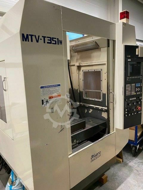
- Model: Miyano Mectron MTV351W (sometimes written MTV-351W)
- Control: Siemens 830DI (ShopMill style)
- Travel: X = 500 mm, Y = 380 mm, Z = 400 mm
- Spindle: up to 12,000 RPM
- Tool changer: double-arm type (for tool magazine)
- BT-30 tooling in one listing
Use these as “target values” when you inspect the machine. If major travel ranges, spindle rpm, or tool capacity differ, ask why (was it modified, downgraded, etc.?).
Inspection & Evaluation Checklist
Here’s a structured walkthrough (cold inspection → power → test → negotiation) you or your technical specialist should carry out on site.
1. Documentation & History
- Ownership & maintenance logs — Check periodic maintenance, past major repairs (especially spindles, drive replacements, encoder overhauls).
- Original manuals, schematics, electrical diagrams, parameter backups — You want the full set. Missing wiring diagrams or control parameter backups is a big negative.
- Software / control backups — Ensure you get all CNC programs, parameter files, macro libraries, custom routines, and the ability to back up or restore the control.
- Modifications / retrofits — Ask for records of any changes (spindle retrofit, drive replacements, control upgrades).
- Load / usage history — Hours under load, tapping cycle count, idle hours, high-stress cycles etc.
- Spare parts & support availability — Check whether replacement parts, especially for spindle bearings, motors, tool changer arms, and control are still available.
- Warranty / spares inclusion — Try to negotiate including critical spares (e.g. spindle bearing set, drives, tool changer parts) or limited warranty on key systems.
2. Visual / Mechanical (Power-off) Inspection
- General cleanliness & signs of care — Excessive rust, corrosion, sludge, neglected lubrication, chipped paint may hint at poor maintenance.
- Castings, frame, structural integrity — Look for cracks, weld repairs, distortions.
- Guideways / linear rails / slide surfaces — Inspect for wear, scratching, scoring, pitting. Remove covers / way wipers to see hidden wear.
- Ballscrews / lead screws / nut assemblies — Check for backlash, side play, wear marks, looseness when manually moved.
- Spindle taper, drawbar, tool interface — Inspect spindle nose, tool retention mechanism; any damage or wear is a red flag.
- Encoders / linear scales / feedback devices — Scratches or contamination of scales or glass encoders will degrade accuracy.
- Seals, bellows, way covers, wipers — These protect vital motion axes; damage or missing parts imply past contamination.
- Coolant / lubrication / flushing systems — Inspect coolant tank, filters, lines, pumps for sludge, leaks, corrosion, clogging.
- Tool changer / magazine — Inspect arms, fingers, rails, alignment, any binding, damage or wear.
- Electrical cabinet, wiring, connectors, drive modules — Open cabinet: look for scorched wires, overheating, wire repairs, cable replacements, clean routing.
- Motors, servo amplifiers, drives — Ensure modules are present, none are missing or replaced in a “jury-rigged” way.
- Sensors, limit switches, wiring harness condition — Check for broken sensors, missing covers, loose or repaired wiring.
- Foundation anchoring, machine base — Check whether anchor points are intact, base plates undamaged, leveling provisions present.
3. Power-Up & Functional Testing
- Safe power-up diagnostics — Monitor voltages, currents, error logs or alarms, drive status.
- Homing / referencing routine — Confirm whether axes home properly without errors.
- Axis motion tests — Jog each axis (X,Y,Z) at slow, medium, fast feed rates; listen/feel for binding, hesitations, noise or unusual friction.
- Rapid traverse test — Move axes rapidly across full travel; watch for loss of synchronization, vibrations, stutters.
- Backlash / reversal error — Reverse motion and measure or monitor positional error in each axis.
- Simultaneous multi-axis moves — Run test moves combining axes (e.g. diagonal, circular interpolation) to check for lag or coordination issues.
- Spindle ramp test — Ramp the spindle through its full rpm range (e.g. up to 12,000 rpm), and listen / feel for vibration, temperature rise, bearing noise.
- Tapping / power tapping function test — Since this is a tapping center, test real tapping cycles (rigid tapping if supported) under load. Check synchronization and backlash compensation.
- Tool change cycles — Run tool change routines at various points in the tool magazine. Observe for speed, misgrips, misalignment, collisions.
- Probe / measurement system (if installed) — If the machine has probing or touch sense devices, run its probing cycle and verify correctness.
- Coolant / spindle through-coolant (if applicable) — Test coolant flow, pressure, leaks, and whether coolant-through-spindle (CTS) works across rpm ranges.
- Warm-up / drift test — Let the machine run idle or under light load for 30–60 minutes, then retest axes for drift, creep, or thermal shift.
4. Metrology & Precision Checks
- Ballbar / circle test — Run circular interpolation tests and analyze deviation to assess geometric integrity.
- Laser interferometry / straightness measurement (if available) — Measure straightness, pitch, yaw, squareness across axes.
- Position repeatability & accuracy tests — Use a gauge or high-precision indicator to verify repeatability over multiple cycles in each axis.
- Cutting test / benchmark part — Run a known test part (e.g. with holes, pockets, surfaces) and verify dimensions and surface finish.
- Reverse side / mirror operations — If possible, use reverse operations to detect systematic alignment errors.
5. Infrastructure / Compatibility Checks
- Foundation, floor strength, anchoring & vibration isolation — The machine’s mass and dynamic loads demand proper support.
- Electrical supply (voltage, phase, frequency) compatibility — Confirm that the facility supply matches the machine (e.g. 3-phase voltage, frequency) and check grounding quality.
- Cooling / chiller / HVAC requirements — Precision machines are sensitive to temperature; verify shop climate control and coolant capacity.
- Compressed air, chip removal, lubrication, exhaust — Ensure your shop supports these auxiliary systems.
- Rigging, doorway access, crane / transport path — Make sure the machine can be moved into place without damage; dimension constraints, crane capacity, clearances.
- Network / communication / CAM interface — Check Ethernet / serial / DNC compatibility, ability to transfer programs, integrate with your CAM systems.
6. Negotiation & Contract Safeguards
- Acceptance / performance testing clause — Include in the purchase agreement a defined acceptance period (e.g. 30 days) after installation where the buyer can reject or demand remediation if specs aren’t met.
- Escrow / holdback — Withhold a portion of payment until after successful test runs and validation.
- Included spares / consumables / warranty — Try to have the seller include a critical spares kit (bearings, seals, sensors) or warranty coverage for key subsystems (e.g. spindle for N hours).
- Transport / insurance responsibility — Clarify who bears the risk in transport. Insist on proper crating, shock protection, insurance.
- Detailed acceptance test specification — In contract, define test protocol (e.g. axis accuracy, tapping performance, tool change cycles) and acceptable tolerances.
- “As-is / where-is” disclaimers — Be cautious of them; try to negotiate removal or limitation of overly broad “no returns” clauses.
Red Flags & Warning Signals
- The seller refuses live inspection or only wants to provide photos/video.
- Missing or incomplete documentation, manuals, backups, or wiring diagrams.
- Unexplained variance from known specs (e.g. significantly less travel, lower spindle rpm without clear reason).
- Spindle vibrations, abnormal sounds, or heat during rpm test.
- Axes that stutter, lag, chatter, or lose position in simultaneous moves.
- Tool changer arms with binding, misalignment, or collision evidence.
- Encoders, linear scales, or guides scratched, contaminated, or poorly maintained.
- Electrical cabinet showing signs of overheating, spliced wiring, or aftermarket hacks.
- No ability to test tapping cycles under load.
- Obsolete or no longer supported components (e.g. obsolete servo modules, drives, or control).
- Seller refusing to include acceptance / performance guarantees.