13/10/2025
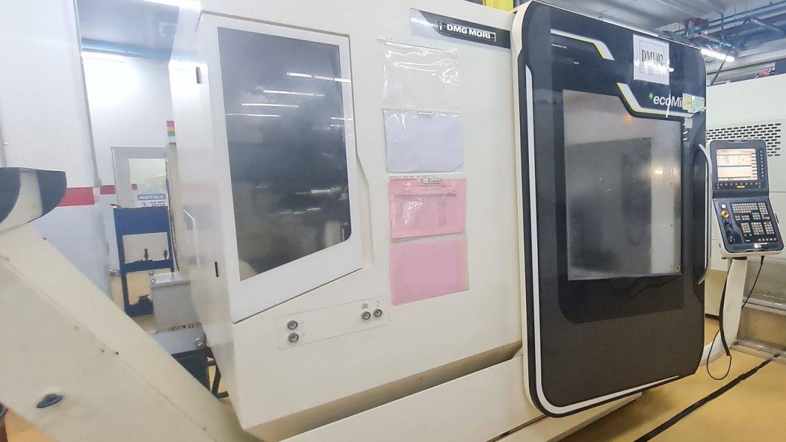
What Should I Pay Attention To When Buying a Second-Hand, Pre-Owned, Surplus, Used DMG MORI ecoMILL 70 CNC Vertical Machining Center 5 Axes made in Germany & Japan?
Buying a used DMG MORI ecoMill 70 (5-axis vertical machining center) is a major investment. You need to verify mechanical integrity, control/electronics health, accuracy, and serviceability. Below is a detailed checklist and pitfalls to watch for.
Reference specs / baseline to compare with
Before inspection, get or confirm the nominal specifications so you know what “good performance” should look like. Some published specs for the ecoMill 70:
| Parameter | Typical / published value |
|---|---|
| X travel | ~ 750 mm |
| Y travel | ~ 600 mm |
| Z travel | ~ 520 mm |
| Tool magazine | ~ 32-position, SK40 or ISO 40 style |
| Spindle speed | Up to 12,000 rpm |
| Table / swivel / axes | B axis −10° to +95°, C axis 360° |
| Table / clamping area | ~ 800 × 620 mm, load ~ 350 kg |
| Rapid traverse (linear axes) | ~ 24 m/min |
| Control options | Siemens 840D, Heidenhain TNC 620 |
Use these as benchmarks during inspection: if the machine falls far short, it may indicate wear, damage, or mis-adjustment.
Detailed inspection & evaluation checklist
Here’s a systematic breakdown of subsystems and tests you should perform (or demand) when evaluating such a machine.
1. Structural / frame / geometric integrity
- Base, casting, frame
– Examine base, cast iron structures, frame joints for cracks, weld repairs, distortions, or evidence of past collisions.
– Check for signs of aging, fatigue, or distortion—especially in heavy load zones.
– Verify that the machine is level and not twisted or bowed in its installed position. - Columns, gantry, B/C axis supports
– Check the rigidity and alignment of columns, overhead cross-members, gantry or support bridges.
– Ensure the B/C axis supports, swivel arms, or rotary parts have not been bent or stressed.
– Look for shim additions, backing plates, or structural patches that might indicate prior misalignment repairs. - Guideway alignment / straightness
– Use straightedges, precision bars, or preferably a laser interferometer to check linear guide alignment across the full range.
– Inspect guide surfaces for wear, scoring, pitting, or embedded chips / debris.
– Move axes slowly and feel for “steps,” binding zones, or nonuniform resistance.
2. Linear motion / axes / ball screws / feed mechanisms
- Ball screws & nuts / coupling / drive train
– Check for backlash, play, or slop in each axis (X, Y, Z, B, C). Reverse direction and see how well it reverses without delay or overshoot.
– Inspect screw threads at both ends and at nut interface for wear, damage, pitting, or rust.
– Check couplings, alignment between motors and screws.
– Listen / feel for uneven motion, grinding, or vibration when moving. - Linear guide / slide condition
– Manually or under control, travel full strokes and look for smoothness vs jerkiness, “sticking spots,” or zones where resistance changes.
– Check for wear marks, corrosion, and signs that chips have scratched or gouged surfaces. - Axis limits, homing, end stops
– Test homing routines, limit switch behavior, and software travel limits.
– Move to near travel extremes and check for interference, mechanical stops, or axis “ghost motion.”
3. Spindle, rotary axes & 5-axis mechanisms
- Spindle & bearings
– Run the spindle at low, medium, and high speeds. Listen for noise, vibration, or roughness.
– Mount a test bar or precision collet and measure radial and axial runout (taper quality).
– After some runtime, measure spindle housing temperature—excess heat suggests bearing wear.
– Inspect the spindle taper, nose, collet interfaces for wear, chips, corrosion.
– If the machine uses direct drive or high-speed designs, check for evidence of surge / torque issues. - Rotary / swivel / B & C axes
– Command rotation (B and C axes) through full range, at different speeds. Watch for jerks, resonance, backlash, or drift.
– Test precision of stops / indexing: rotate to a position, move away, return, measure deviation.
– Under simultaneous motion (e.g. combined linear + rotary), observe dynamic behavior (e.g. vibration, coupling effects).
– Inspect bearings, gearboxes, coupling (worm, harmonic, direct-drive, etc.) for play or wear. - Tool orientation / head / kinematics
– If the machine has a moving head or tilting head, test that mechanism—as it adds complexity and failure modes.
– Check wiring, cabling, seals, and mechanical joint integrity in those moving parts.
4. Control, electronics, software & cabling
- Power-up / boot / diagnostics
– Watch the machine boot. Note any error codes, missing modules, failed I/O, warnings, or discrepancies.
– Access diagnostics, I/O status screens, alarm logs.
– Inspect control cabinet: fans, heatsinks, wiring quality, signs of overheating, dust accumulation, or corrosion. - Servo drives, motors, feedback / encoders
– Inspect drive modules for signs of stress (heat, discoloration, loose connectors).
– Run axes and check motor noise, hum, or vibration.
– Inspect encoder cables and connectors: shielded, properly routed, no strain or damage.
– During motion, check for feedback signal errors or dropouts. - Software / parameter integrity
– Ask for a backup of all parameters / settings, calibration / compensation tables. Verify they are intact and restorable.
– Check for firmware version, custom patches, or “nonstandard” modifications.
– Test parameter editing, save / restore behavior, and see if compensation settings (thermal compensation, axis linearization, backlash correction) are functional. - Homing, reference, interpolation, tool cycles
– Run typical 5-axis motion programs (linear + B + C) to verify smooth interpolation and motion control.
– Test tool change sequences, look for collisions, delays, mis-indexing.
– Test feedrate override, lookahead, acceleration/deceleration behaviors. - Safety, interlocks, limits
– Test e-stop, guard door interlocks, axis limits, motion disable upon guard open.
– Try opening covers / doors (in a safe mode) to see if machine halts.
5. Accuracy, calibration & metrology tests
- Geometric validation / volumetric accuracy
– Use laser interferometry, ballbar, or precision measurement devices to test straightness, angular errors, linear axis accuracy.
– For a 5-axis machine, test volumetric accuracy (i.e. how positional error accumulates in combined axes) — often the real test of machine quality.
– Move to a given 3D point, retract, return, and measure return accuracy. - Thermal drift / repeatability under load
– Run the machine for a period (under moderate load) and re-check positions to see if error grows or drifts.
– Check for warm-up distortions or axis drift over time. - Production / “real” part trial
– Run a sample part (representative of your intended work) through full 5-axis motions. Inspect final dimensions, surface finish, alignment across faces.
– Repeat multiple runs to check consistency.
6. Tooling, tool changer, spindle interface & consumables
- Tool changer / magazine
– Cycle tool changes many times. Look for failures, mis-indexing, slow operations, sensor problems, collisions.
– Inspect magazine rail mechanics, locks, sensors, slides for wear or play. - Tool holder integrity / taper runout
– Mount test tool holders, measure runout, check repeatability of tool-to-tool mounting.
– Inspect the taper faces, clamp surfaces, retention systems for wear or damage. - Tool cooling / through-spindle coolant / coolant plumbing
– If the machine supports through-spindle coolant or side-coolant for tools, test the coolant paths (pressure, leaks, blockages).
– Inspect plumbing, seals, hoses.
7. Maintenance history, wear & usage profile
- Age, hours, usage counts
– Ask for power-on hours, spindle hours, cycle counts, usage logs.
– Compare with how intensively you plan to use the machine. - Maintenance / repair logs
– What components have been replaced or serviced (bearings, encoders, linear guides, drives, control modules)?
– Any crash events, collisions, overloads — how they were repaired.
– Environment of operation (dust, humidity, temperature, coolant practices) and maintenance discipline (cleaning, lubrication). - Modifications / retrofits
– Be cautious of custom modifications, unapproved retrofits, or “band-aid” repairs. These may signal hidden issues.
8. Spare parts, support, and ecosystem
- Parts availability
– Are original DMG MORI parts still available for the ecoMill 70 line (drives, spindles, encoders, axes, control modules)?
– Are there local or regional suppliers or service houses capable of supporting this machine? - Documentation / manuals / backups
– Make sure you receive operator manuals, maintenance manuals, electrical schematics, wiring diagrams, calibration & compensation tables.
– Ensure parameter backups, control customizations, motion profiles are included. - Support & service network
– Is there a DMG MORI service presence in your country (Turkey) or Europe?
– Check how long lead times are for critical parts and whether remanufactured spares are viable.
9. Shop readiness & infrastructure compatibility
- Electrical / power supply
– Confirm that your shop can supply the correct voltage, phase, current (amps) with stable supply.
– Consider adding power conditioning / surge protection if needed. - Foundation, leveling, and rigidity
– The machine must sit on a solid, rigid, flat floor. Vibrations or flex in foundation degrade accuracy.
– Check anchor points, bolt holes, leveling arrangements. - Space / clearance / crane & rigging
– Ensure adequate clearance around the machine for maintenance, tool changes, access to axes, overhead lifting / crane for parts & spindle removal.
– Assess how the machine will be moved in/out and whether your facility can support it. - Cooling, ventilation, heat management
– Drive electronics, control cabinets, and spindle cooling generate heat. The workshop must ventilate or cool appropriately.
– Chip / coolant management systems (filtration, conveyors, sump, coolant chiller) must be in place or do-able. - Safety / guarding / compliance
– Guards, interlocks, light curtains, emergency stops must meet local safety regulations.
– The machine should safely disable motion when doors or guards are open.
10. Pricing, negotiation & risk mitigation
- Estimate the cost of likely repairs (bearing replacements, rework of axes, control modules, calibration) and deduct from the asking price.
- Require a test / acceptance clause so that you can verify performance after installation with your own test parts.
- Demand inclusion of spare parts, tooling, backup modules, parameter backups.
- Bring along a 5-axis machining / metrology expert for inspection if possible.
- Include shipping, installation, alignment, calibration, and acceptance costs in your total investment budget.
- Ask for a performance guarantee, limited warranty, or liability clause for hidden defects.
- Check references from prior buyers of the same model and ask about common failure modes or quirks.
11. Red flags / deal-killing defects
If you discover many of the following, the machine’s risk may be too high unless priced deeply discounted:
- Cracked or welded repairs in critical structures (frame, columns, gantry)
- Severe wear or scoring on guideways or linear axes
- Excessive backlash, slop, or non-repeatable motion in axes
- Spindle bearing noise, high runout, heating, taper damage
- Rotary/trunnion axes that bind, jitter, or have large indexing errors
- Drives or electronics with repeated faults, missing modules, or unreliable performance
- Control parameter corruption, missing backups, or incompatible software
- Seller refusing full test runs or denying access to run programs
- No documentation, wiring diagrams, parts catalogs, or calibration data
- No support network or severely delayed parts supply
- Environmental damage (rust, moisture, corrosion inside electrical enclosures)
- Mismatch between claimed vs actual motion or performance
- Safety systems not working or bypassed