What is Swarf Processing?
Swarf processing refers to the systematic collection, separation, treatment, and recycling of metal swarf (also known as chips or cuttings) generated during machining operations in the metalworking and CNC machine tool sectors. Swarf consists of small, irregular metal fragments produced by cutting, milling, turning, or grinding processes, often mixed with cutting fluids (coolants), lubricants, and contaminants like fines or debris. The goal of swarf processing is to recover valuable materials (e.g., metals and fluids), minimize waste, ensure environmental compliance, and reduce operational costs. It’s a critical aspect of sustainable manufacturing, as untreated swarf can pose disposal challenges and resource losses.In technical terms, swarf processing transforms heterogeneous waste streams into reusable or sellable outputs, leveraging mechanical, thermal, or chemical methods. Below, I’ll break it down step-by-step, focusing on its application in metalworking and CNC environments.1. Swarf Generation in Metalworking and CNC Operations
- Context: In CNC lathes, mills, or grinders, tools remove material from workpieces (e.g., aluminum, steel, titanium) at high speeds, producing swarf in forms like curly chips, fines, or powder. Coolants (water- or oil-based emulsions) are used to reduce friction, dissipate heat, and flush chips away.
- Challenges: Swarf volume can reach 20-50% of the workpiece mass in high-material-removal-rate processes. It clogs machines, contaminates fluids, and requires safe handling to avoid fire risks (from flammable coolants) or health hazards (e.g., metal dust inhalation).
- Typical Composition: 70-90% metal, 5-20% coolant, and traces of abrasives or oxides.
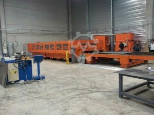
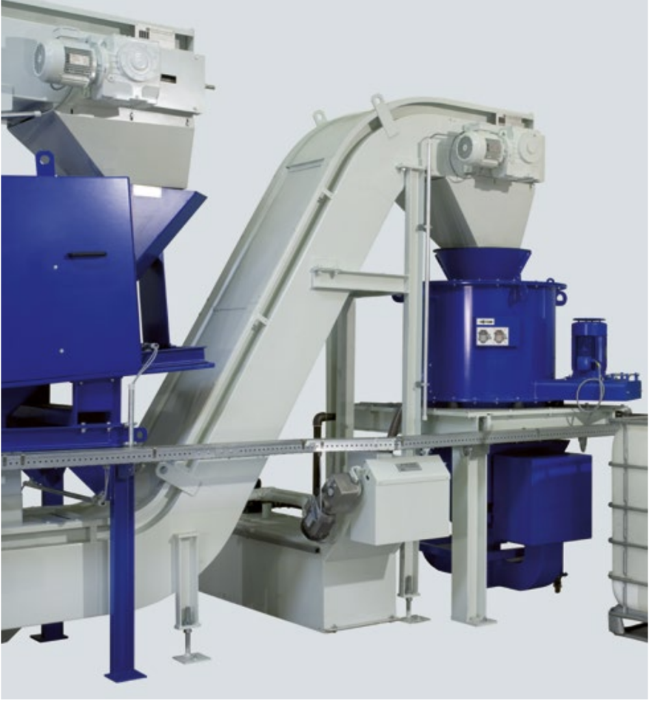
2. Key Stages of Swarf ProcessingSwarf processing is typically a multi-stage, automated workflow integrated into production lines. Based on the image you provided—which depicts a modular system with hoppers, conveyors, centrifuges, and storage tanks—here’s a technical overview of the process:
- Collection and Initial Handling:
- Swarf is captured at the machine tool via chip conveyors (e.g., hinged steel belts or drag chains) or chip boxes. In your image, the blue hoppers and gray silos serve as intake points.
- Gravity-fed or vibratory feeders transport swarf to a central processing unit, preventing buildup in machine sumps.
- Separation:
- Mechanical Separation: Uses screens, magnets, or air classifiers to segregate ferrous/non-ferrous metals from non-metallics. For example, magnetic drums pull out steel chips.
- Centrifugal Separation: High-speed centrifuges (e.g., 3,000-6,000 RPM) spin swarf to separate solids from liquids via centrifugal force. The G-force (up to 3,000g) flings heavier metal particles outward while lighter coolant drains inward. In the image, the blue cylindrical unit is likely a decanter centrifuge, handling wet swarf at rates of 1-10 tons/hour.
- Filtration: Tramp oil separators or coalescers remove emulsions from free oils, achieving 99% purity in recovered coolant.
- Dewatering and Drying:
- Pressing/Compacting: Hydraulic presses (pressures up to 200 bar) squeeze swarf to <5% moisture content, forming briquettes or blocks for easier transport. This reduces volume by 80-90%.
- Thermal Drying: For oilier swarf, heated screw conveyors or vacuum dryers evaporate fluids at 100-150°C, recovering vapors for reuse. The white control panel in your image likely monitors temperature and pressure here.
- Purification and Recycling:
- Chemical Treatment: Additives neutralize emulsions or remove contaminants, enabling coolant reuse in closed-loop systems.
- Metal Recovery: Sorted swarf is melted in furnaces or sold to recyclers. For instance, aluminum swarf yields 95% recoverable metal, offsetting raw material costs by $0.50-2.00/kg.
- Waste Minimization: Dry swarf is palletized; liquids are filtered to <10 ppm solids for machine recharge.
3. Technical Components in a Typical System (As Seen in Your Image)Your provided image illustrates an industrial swarf processing line, likely from a manufacturer like Stuhlregal or Alfa Laval. Here’s a component breakdown:
| Component | Description | Function in Swarf Processing |
|---|---|---|
| Gray/Blue Hoppers (Intake) | Funnel-shaped silos with motors. | Collect and meter swarf from CNC machines; vibrate to break up clumps. |
| Inclined Conveyor (White Belt) | Chain-driven belt with cleats. | Elevates wet swarf to processing units; handles 5-20 m/min speeds, preventing spills. |
| Blue Cylindrical Unit (Centrifuge/Mixer) | Vertical drum with gauges and outlets. | High-G separation of metal from coolant; outputs dry cake (solids) and clean filtrate. |
| White Control Box | Digital display with sensors. | PLC-based automation for flow rates, RPM, and alarms (e.g., overload detection). |
| Blue Tank and IBC (Output) | Storage drums on wheels. | Collect recovered coolant for reuse; IBCs (intermediate bulk containers) hold 1,000L batches. |
| Support Frames (Blue/White) | Welded steel structures. | Ensure stability for 24/7 operation; vibration-dampened for precision environments. |
4. Benefits and Metrics in Metalworking/CNC Sectors
- Efficiency Gains: Reduces coolant consumption by 70-90%, extending tool life by 20-50% via cleaner fluids.
- Cost Savings: Recovers $100-500/ton in metals; payback on systems (e.g., $50K-200K installs) in 1-2 years.
- Sustainability: Complies with regulations like EU Directive 2000/53/EC on waste; cuts landfill use by 95%.
- Scalability: Systems handle 100 kg/hour (small shops) to 50 tons/hour (aerospace fabs), with IoT integration for predictive maintenance.
In summary, swarf processing turns machining byproducts into assets, optimizing CNC workflows through physics-based separation (e.g., centrifugation via
F=mω2rF = m \omega^2 rF = m \omega^2 r, where
ω\omega\omega is angular velocity). For deeper dives, standards like ISO 14001 guide implementations in these sectors.