What is Metal Chip Wringer/Centrifuge designed to effectively separate metal chips from cutting fluids?
A Metal Chip Wringer, also known as a Chip Spinner or Chip Centrifuge, is an industrial separation device engineered for the metalworking industry. It leverages centrifugal force to dewater wet metal chips (swarf or turnings) generated during machining processes like milling, turning, or grinding, effectively recovering cutting fluids (coolants or oils) for reuse. This results in drier scrap metal that commands a higher market value (typically 20-50% premium over wet chips) while reducing disposal costs and ensuring compliance with environmental regulations (e.g., EPA guidelines on fluid transport). Capacities range from 500 lb/hr for low-volume units to 10,000 lb/hr for high-throughput models, with residual moisture content as low as 2% achievable, depending on chip material (e.g., aluminum, steel, copper) and fluid type.Technical Principle: Centrifugal SeparationThe core mechanism relies on centrifugal force to exploit the density and size differences between solid metal particles and liquid cutting fluids. Unlike gravity-based settling, which is slow and inefficient for fine emulsions, centrifugation accelerates separation by 600-700 times the force of gravity (g-forces).Key Physics
- Centrifugal Force Generation: The formula for centrifugal force is Fc=mω2rF_c = m \omega^2 r
F_c = m \omega^2 r, where:- ( m ) is the mass of the chip/fluid particle,
- ω\omega
\omegais the angular velocity (rad/s) of the rotating bowl (typically 1,000-3,000 RPM), - ( r ) is the radius of the bowl (e.g., 8-20 inches for common models).
- Density Gradient Separation: Chips and fluid enter the rotor as a slurry. Under rotation, particles stratify by density: solids form a “cake” on the periphery, while liquids form a clarified inner layer. The separation efficiency follows Stokes’ law adapted for centrifugation: settling velocity v=2r2(ρs−ρl)ω2r9μv = \frac{2 r^2 (\rho_s – \rho_l) \omega^2 r}{9 \mu}
v = \frac{2 r^2 (\rho_s - \rho_l) \omega^2 r}{9 \mu}, where ρs\rho_s\rho_sand ρl\rho_l\rho_lare solid/liquid densities, and μ\mu\muis fluid viscosity. Lower viscosity fluids (e.g., oils) separate faster than emulsified coolants. - Recovery Efficiency: Fluid reclamation rates exceed 97-98%, with chip dryness <2-4% residual moisture. This minimizes emulsion breakdown and bacterial growth in recycled fluids.
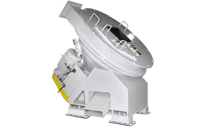
Design and ComponentsMetal Chip Wringers are robust, vibration-dampened units (often with isolators for low-frequency operation) constructed from hardened steel or stainless steel for wear resistance. Common configurations include vertical, horizontal, or diagonal-axis designs, with the diagonal type aiding gravity-fed flow.
| Component | Function | Technical Details |
|---|---|---|
| Feed Hopper/Chute | Receives wet chips from conveyors or machine tools. | Gravity or pneumatic feed; straight-line design prevents choke points. Throughput: 330-1,653 lb/hr per model. |
| Rotating Bowl/Drum | Generates centrifugal force; lined with perforated screen (slots 0.02-0.08 inches). | Diameter: 16-40 inches; RPM: 1,200-2,800; balanced for continuous duty (24/7 operation). Fan blades on top create airflow for pneumatic discharge up to 100 ft. |
| Screen Liner | Filters solids from liquids. | Machined slots or woven mesh; self-cleaning via reverse rotation or compressed air bursts to prevent clogging. Adjustable for chip size (fine swarf to stringy turnings). |
| Drive System | Powers rotation. | Electric motor (5-20 HP) with VFD (variable frequency drive) for speed control; reversing feature extends screen life by 2-3x. |
| Discharge Mechanisms | Separates outputs. | – Fluid: Drains via bottom outlet to reclamation tank. – Solids: Coasting stop reduces g-force, allowing chips to slide out; pneumatic expulsion or gravity drop to conveyor/briquetter. |
| Controls | Automates operation. | PLC with touch interface; sensors for load balancing, imbalance shutdown, and auto-flush (e.g., air purge for blockages). |
Operational Modes
- Batch: Manual loading/unloading for low volumes (e.g., Model 16CD).
- Continuous: Automated feed/discharge for high volumes (e.g., VBU-Series), with inline integration into chip processing lines.
Process Flow
- Input: Wet chips (moisture 10-20%) enter via hopper, propelled by conveyor.
- Acceleration: Material contacts the spinning bowl base, flung outward at 600-700g.
- Separation: Chips press against the screen, forming a cake; fluid shears through perforations (radial flow) into a collection sump.
- Discharge: Bowl slows; chips discharge via gravity/pneumatics. Fluid recirculates (filtered if needed).
- Maintenance Cycle: Periodic reverse spin or air cleaning clears residue; no daily disassembly required.
Advantages and Applications
- Economic: Reduces coolant purchases by 90%; increases scrap value (dry chips fetch $0.20-0.50/lb premium).
- Environmental: Minimizes wastewater (up to 98% recovery); complies with ISO 14001.
- Versatility: Handles ferrous/non-ferrous chips; integrates with briquetters for further compaction.
- Limitations: Less effective for highly viscous emulsions (may need pre-filtration); initial CAPEX $20,000-100,000, with ROI in 6-12 months via savings.