What is Ring Coiling Machine for the Manufacture of Ringsand Wave Springs from Profiled Wire?
A ring coiling machine, particularly one designed for the manufacture of rings (such as retaining rings or snap rings) and wave springs from profiled wire, is a specialized CNC (Computer Numerical Control) machine tool used in precision wire forming. These machines are integral to industries like automotive, aerospace, medical devices, and electronics, where high-precision components are required for applications such as shaft retention, sealing, or spring loading. Unlike standard round-wire coilers, these machines are optimized for profiled wire—material with non-circular cross-sections, such as rectangular, square, trapezoidal, or flat strips—which allows for enhanced load-bearing capacity, reduced material usage, and custom geometries in the final product.The term “ring coiling machine” often refers to models like the WAFIOS SNA series, which exemplify the technology. These machines enable the production of single- or multi-turn rings (closed-loop structures for retention) and wave springs (helical springs with undulating waves for axial compression in limited spaces) on a single platform, offering flexibility, high output rates, and minimal waste. The process leverages edgewinding or multi-roller coiling techniques to form the wire into precise shapes without dedicated stamping dies, reducing tooling costs and enabling rapid customization.Key Technical ComponentsRing coiling machines for profiled wire typically feature a modular, all-electric or servo-driven architecture for precise control. Below is a breakdown of the primary components:
- Wire Feeding and Straightening System:
- Profiled wire (e.g., rectangular cross-section with dimensions like 0.5 mm × 2 mm) is fed from a spool via a powered decoiler or payoff reel. The wire diameter range is typically 0.15–16 mm, with outer diameters for products up to 320 mm for rings and 250 mm for wave springs.
- Straightening rollers or dies align the wire to prevent buckling during coiling. For profiled wire, specialized guides accommodate the non-uniform cross-section to maintain orientation and avoid twisting.
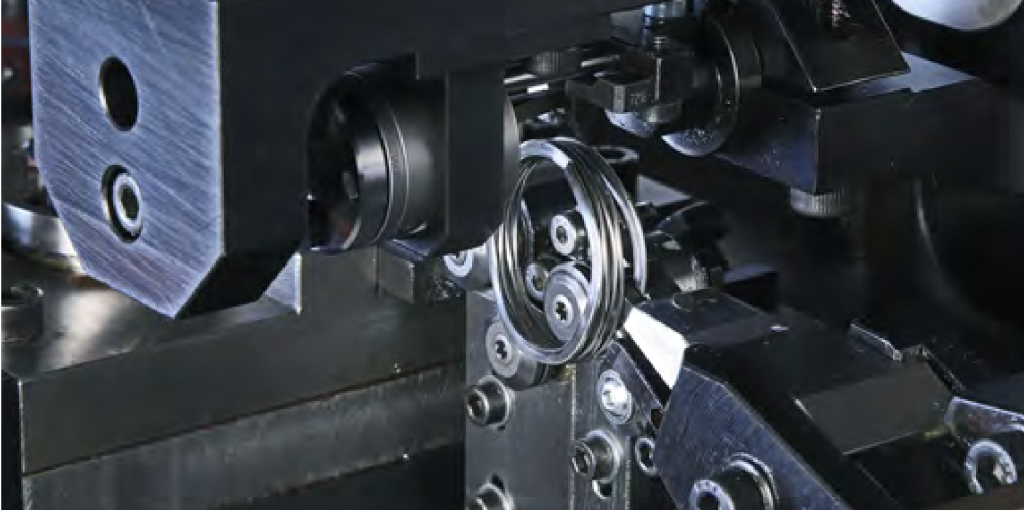
- Coiling Unit:
- The core mechanism is a robust multi-roller coiling assembly, often with 3–5 adjustable rollers (e.g., up to 5 in the WAFIOS SNA series). These rollers rotate the wire into a helical or circular path, forming the ring or wave geometry.
- For rings: The wire is coiled into a flat, closed loop (one-turn or multi-turn) using an arbor (mandrel) to define the inner diameter. The rollers apply controlled pressure to achieve circular or oval shapes with tolerances as tight as ±0.01 mm.
- For wave springs: An optional CNC pitch axis introduces sinusoidal variations in the wire pitch, creating waves (e.g., 3–12 waves per turn). This is achieved by varying the feed rate and roller positioning, allowing for right-hand or left-hand coiling. Wave heights can be customized (e.g., 0.5–5 mm) via software presets.
- All-electric servo motors drive the axes, minimizing the “flowering effect” (radial expansion during coiling) through intelligent compensation algorithms. This ensures concentricity and reduces scrap rates to near zero.
- Cutting and Separation Mechanism:
- A height-adjustable cutting unit (e.g., shear or rotary blade) is mounted on a linear slide. For rings, it severs the wire after forming the loop, often plunging into the coil for clean separation.
- In wave spring mode, the cutter retracts to avoid interference, and separation occurs by notching or plunging into the formed waves. This design supports continuous production without halting the coiling process.
- Precision is critical for profiled wire, as the non-uniform shape requires blade angles matched to the profile to prevent burrs or deformation.
- Control and Programming System:
- CNC controllers (e.g., WPS 3.2 EasyWay software) manage up to 6–8 axes, including feed, coiling, pitch, and cutter motion. Programming involves selecting presets for geometry (e.g., number of turns, wave height, outer diameter) and material properties (e.g., steel, stainless, or alloy profiles).
- Features like auto-setup wizards and simulation reduce changeover time to under 10 minutes. Sensors monitor tension, diameter, and pitch in real-time, with feedback loops adjusting for material variations (e.g., springback in high-carbon profiled wire).
- Auxiliary Systems:
- Tension control maintains consistent wire pull (e.g., 5–50 N), preventing slippage in profiled sections.
- Ejection and collection: Pneumatic or mechanical pushers remove finished parts to a conveyor or bin.
- Safety and ergonomics: Enclosed guards, user-friendly interfaces, and optional automation (e.g., robotic loading) enhance uptime.
Manufacturing Process: Step-by-Step Technical ExplanationThe process transforms profiled wire into rings or wave springs through a sequence of automated steps, emphasizing precision forming to achieve mechanical properties like high fatigue resistance and load capacity. Here’s a technical breakdown:
- Material Preparation:
- Profiled wire is loaded into the decoiler. The cross-section (e.g., rectangular for optimal stacking in wave springs) is oriented via guides. Initial tension is set based on material yield strength (e.g., 800–1500 MPa for spring steel).
- Feeding and Initial Forming:
- Servo-driven feed rollers advance the wire at speeds up to 60 m/min. Straightening ensures flatness, critical for profiled wire to avoid edge burrs.
- Coiling Phase:
- The wire enters the coiling zone, where rollers and an arbor rotate it. For a ring: The pitch is near-zero, forming a tight coil with outer diameter Do=Di+2tD_o = D_i + 2t
D_o = D_i + 2t, where DiD_iD_iis inner diameter and ( t ) is wire thickness. Multi-turn rings stack layers for added strength. - For wave springs: The pitch axis modulates the helix angle θ\theta
\theta, creating waves via h=Psin(ω)h = P \sin(\omega)h = P \sin(\omega), where ( h ) is wave height, ( P ) is pitch, and ω\omega\omegais wave frequency (e.g., 2π × waves per turn). This produces a spring rate k=Gd48D3Nk = \frac{G d^4}{8 D^3 N}k = \frac{G d^4}{8 D^3 N}adapted for wave geometry, where ( G ) is shear modulus, ( d ) is effective wire diameter, ( D ) mean diameter, and ( N ) active coils. - Compensation software adjusts for elastic recovery: During coiling, the “flowering” (diameter increase by 1–5%) is counteracted by over-bending, using finite element models in the controller.
- The wire enters the coiling zone, where rollers and an arbor rotate it. For a ring: The pitch is near-zero, forming a tight coil with outer diameter Do=Di+2tD_o = D_i + 2t
- Cutting and Finishing:
- The cutter activates at the programmed length, applying shear force F=τAF = \tau A
F = \tau A, where τ\tau\tauis shear stress and ( A ) is cross-sectional area. For profiled wire, the blade aligns with the thinner dimension to minimize force (e.g., <500 N). - Post-cut, parts may undergo heat treatment (e.g., stress relieving at 200–400°C) or grinding for end squaring, though the machine focuses on primary forming.
- The cutter activates at the programmed length, applying shear force F=τAF = \tau A
- Quality Control:
- Inline sensors measure dimensions (e.g., laser gauging for diameter ±0.005 mm) and reject defects. Output rates: Up to 100–500 parts/min for small rings, depending on complexity.
Advantages and Technical Considerations
- Precision and Flexibility: Tolerances down to ±0.01 mm enable applications in high-load environments (e.g., wave springs with 10,000+ cycles). Profiled wire reduces volume by 50% compared to round wire while maintaining force.
- Efficiency: No material waste (vs. stamping), and multi-part production on one machine increases throughput by 20–30%.
- Challenges: Profiled wire requires precise tooling to handle anisotropy (directional properties), and high-speed operation demands robust vibration damping to avoid resonance.