What is Lead/Traction Spindle Lathe?

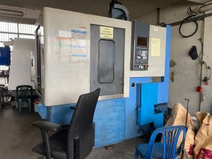
Understanding Lead/Traction Spindle Lathes in Metalworking Based on the provided image and the terminology “Lead/Traction Spindle Lathe,” this refers to a specific type of conventional engine lathe (also known as a metalworking lathe) designed for precision machining in the metalworking sector. The image depicts a geared headstock lathe model from Geared Head Wolf (likely the G9290 or similar, as indicated by the labeling on the machine’s headstock and apron), which appears to incorporate features associated with “guide and traction spindle” configurations. These terms are often used interchangeably in European manufacturing contexts (e.g., by brands like Optimum Maschinen or Wolf) to describe lathes with a robust, guided spindle system for enhanced stability and precision during operations like turning, threading, and facing.In technical terms, a Lead/Traction Spindle Lathe is a manual or semi-automatic metal lathe where the spindle (the rotating shaft that holds the workpiece) is engineered with a “traction” or “guided” mechanism. This typically involves a hollow spindle (for passing long stock through it) combined with a precision lead screw system for synchronized tool feeding. The “traction” aspect emphasizes the spindle’s ability to provide high-traction drive (via geared or belt systems) for consistent torque and speed, while “lead” refers to the integration of a lead screw for accurate longitudinal and threading feeds. These lathes are optimized for metalworking applications, such as producing cylindrical parts, threads, and tapers from materials like steel, aluminum, or alloys. They are distinct from basic bench lathes due to their heavier construction, larger spindle bores, and advanced gearing for industrial use.Below, I’ll explain the technical aspects step by step, focusing on the metalworking sector. This draws from standard lathe engineering principles, where such machines are used for subtractive manufacturing processes like turning (removing material via a rotating workpiece and stationary tool).1. Core Components and Their Technical FunctionsA Lead/Traction Spindle Lathe consists of several key assemblies, all mounted on a rigid bed for vibration-free operation. The design ensures high concentricity (typically <0.01 mm runout) and precise control, critical for metalworking tolerances.
- Bed: The foundational structure, usually made of gray cast iron or ribbed prism bed for damping vibrations. It features hardened and ground guideways (V- or flat-shaped) along the Z-axis (longitudinal direction). In the image, the black bed with silver ways supports the carriage and tailstock. Technical specs: Guideways are often induction-hardened to 45-55 HRC for wear resistance, with a length of 1-2 meters for workpieces up to 1-2 m between centers. This setup allows for heavy cuts (up to 5-10 mm depth) on metals without deflection.
- Headstock (Geared Head): Houses the main spindle, motor, and gearing system. The “geared head” (visible in the image as the multi-lever control panel labeled “G9290”) uses a multi-speed gearbox (e.g., 8-16 speeds from 50-2000 RPM) for variable spindle speeds.
- Spindle: The rotating core, driven by an electric motor (typically 2-7.5 kW, 3-phase). It has a hollow bore (e.g., 50-100 mm diameter in models like the G9290) for “through-spindle” work, allowing long bars (e.g., 3-6 m) to be fed axially for continuous turning. The “traction” feature refers to the spindle’s high-torque drive via helical gears or belts, providing consistent pulling force (traction) on the workpiece to prevent slippage during heavy metal removal. Bearings are precision roller or angular contact types (e.g., ISO P4 class) for speeds up to 3000 RPM and runout <0.005 mm.
- Nose Type: Camlock (e.g., DIN ISO 702-2 No. 4-6), as seen in the image’s spindle end, for quick chuck mounting without re-centering. This enables secure holding of workpieces up to 200-400 mm diameter (swing over bed).
- Carriage and Apron: The movable platform for the tool. Includes:
- Saddle and Cross-Slide: Rides on the bed ways via gibs (adjustable brass strips for backlash elimination). The cross-slide moves perpendicular to the spindle axis (X-axis) for facing operations, with a feedscrew (Acme thread, 4-6 mm pitch) for 0.01-0.1 mm increments.
- Compound Rest: Pivots for taper turning (up to 10° angles).
- Apron: Houses controls for feeds. The “lead” mechanism integrates a lead screw (separate from the feed rod) for threading. The lead screw is a precision Acme or trapezoidal thread shaft (e.g., 6-12 mm diameter, multi-start for high-speed ops) driven by the spindle via change gears or a quick-change gearbox. This synchronizes carriage movement with spindle rotation, enabling thread pitches from 0.2-28 mm (metric) or 4-112 TPI (inch).
- Tailstock: Offsettable for tapers, with a quill (non-rotating barrel, 50-75 mm travel) holding centers or drills. Quill diameter ~50 mm, Morse Taper 3-5 bore. In the image, it’s the right-side assembly with a handwheel.
- Leadscrew and Feed System: The hallmark of the “lead” functionality. The leadscrew connects to the spindle via a gear train (e.g., tumbler gears for direction reversal). For threading, half-nuts (clutch) engage the carriage to the leadscrew, moving it at a ratio matching the desired pitch (e.g., for M10x1.5 thread, leadscrew advances 1.5 mm per spindle revolution). Traction ensures smooth engagement without backlash, using anti-friction nuts (e.g., bronze or ball-type). Feed rates: 0.05-1 mm/rev for longitudinal turning.
- Coolant and Safety Features: Flood coolant system (pump-driven) for chip evacuation and thermal stability during metal cutting. Emergency stops (red button in image) and splash guards prevent hazards.
2. Technical Operation in MetalworkingIn the metalworking sector, these lathes perform subtractive processes on ferrous/non-ferrous metals, achieving surface finishes of Ra 1.6-3.2 µm and tolerances ±0.01 mm.
- Setup: Mount workpiece in chuck/collet on spindle or between centers (headstock live center and tailstock dead center). Select spindle speed via gearbox levers (e.g., based on material: 200-500 RPM for steel, higher for aluminum to avoid built-up edge).
- Turning Process: Spindle rotates workpiece (e.g., 100-1000 RPM). Tool (HSS or carbide insert, held in tool post) advances via handwheel or power feed. Longitudinal feed uses the feed rod for general turning; cross-feed for diameter reduction. Depth of cut: 0.5-5 mm, depending on power (e.g., 3-5 HP motor removes 10-20 cm³/min of metal).
- Threading (Lead Function): Engage half-nuts to leadscrew. Gearbox sets pitch (e.g., via Norton cone gears for infinite ratios). Spindle rotation drives carriage at exact lead (advance per rev), cutting threads with a 60° tool. Traction spindle maintains constant torque (e.g., 100-500 Nm) to handle interrupted cuts without stalling.
- Advanced Features: Gap bed (removable section for large-diameter work) and rapid traverse (hand-levered) for efficiency. Digital readouts (DRO, as in the image’s display) provide position feedback for ±0.001 mm accuracy.
- Kinematics and Power Transmission: Power from motor to spindle via belt/gears (traction drive for low-speed/high-torque). Leadscrew gearing: Spindle RPM × gear ratio = carriage speed (mm/rev). Example: For 1 mm pitch thread at 200 RPM spindle, carriage advances 200 mm/min.
3. Advantages in Metalworking Sector
- Precision and Versatility: Ideal for prototyping shafts, bushings, and fittings in automotive/aerospace. Hollow spindle handles long stock (e.g., gun barrels) without unsupported overhang.
- Durability: Geared head provides full power at all speeds (unlike belt drives), suitable for tough metals like titanium.
- Efficiency: Quick-change gearbox reduces setup time (5-10 min for thread changes). Compared to CNC lathes, these are cost-effective for low-volume jobs.
- Specs from Similar Models (e.g., G9290-like): Swing over bed: 300-400 mm; Centers: 900-1500 mm; Spindle bore: 80 mm; Speeds: 12 steps, 45-1800 RPM; Weight: 1000-2000 kg for stability.
4. Limitations and Maintenance
- Manual operation limits high-volume production (vs. CNC).
- Requires skilled setup to avoid backlash or vibration.
- Maintenance: Lubricate leadscrew/gears weekly; check spindle bearings annually for <0.002 mm runout. Align bed ways if deflection >0.02 mm/300 mm.
In summary, a Lead/Traction Spindle Lathe like the one in the image is a robust, geared-head engine lathe optimized for precise metal removal through synchronized spindle rotation and leadscrew-driven feeds. It’s essential in job shops for creating rotationally symmetric parts, offering a balance of power, accuracy, and affordability in the metalworking industry.