26/08/2025
What is Cylinder Boring-Resurfacing Machine?

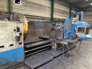
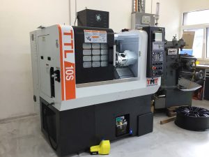
Cylinder Boring-Resurfacing Machine is a precision machine tool used in engine reconditioning to (1) enlarge and true worn/oval cylinder bores to a specified diameter and geometry, and (2) re-machine the deck surface (block top) for gasket sealing and squareness to the crank centerline. It combines a boring bar/spindle and a resurfacing head on one column with a powered X-Y worktable and rigid fixturing for engine blocks.
How it works
1) Cylinder boring
- The block is clamped and leveled to the crank axis; centering pilots locate each bore.
- A vertical boring spindle (micrometric bar with indexable cutters) feeds through the bore.
- Typical sequence: rough cut → semi-finish → finish cut, leaving a controlled allowance (~0.02–0.08 mm) for the later honing step that sets final size and cross-hatch.
- Goals: roundness, straightness, and perpendicularity of the bore to the deck/main line.
2) Deck resurfacing
- A milling/fly-cut head with PCD/CBN tooling (or grinding wheel on some models) traverses the deck.
- Feed/speed and tool type are chosen to hit the gasket’s surface-finish spec:
- MLS gaskets: typically Ra ~0.3–0.8 µm (very smooth).
- Composite/copper: typically Ra ~1.5–3.2 µm (verify OEM spec).
- The machine references the deck to the main bore line to restore parallelism/squareness.
Key subsystems
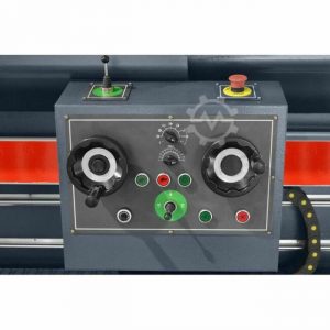
- Rigid column & saddle, powered Z for spindle; powered table X/Y for position and surfacing passes.
- Boring spindle/bar with fine diameter adjust, dial/servo readout.
- Resurfacing head (fly-cutter with PCD/CBN) or grinding head.
- Fixturing: universal V-supports, parallels, end-stops, torque-plate capability.
- Coolant & filtration, chip evacuation, guards, interlocks.
- Measuring: dial bore gauge, probe/centering device, deck height indicators.
Typical capabilities (model-dependent)
- Bore diameter range: ~Ø30–170 mm (light-duty) up to >Ø300 mm (diesel blocks).
- Accuracy: bore size to ±0.005–0.01 mm, straightness/roundness ≤ 0.01–0.02 mm over stroke.
- Deck flatness: ≤ 0.02 mm across length with proper setup.
- Surface finish: controllable by insert, nose radius, feed, and speed as above.
Process considerations & best practices
- Use torque plates during boring for high-performance blocks to simulate head clamping.
- Always hone after boring to final size and geometry; boring alone does not establish plateau finish.
- For aluminum blocks with steel liners vs parent-bore, choose inserts and cutting data accordingly.
- Maintain spindle/slide geometry (tram/squareness); verify with test cuts and gauge blocks.
- Choose CBN for cast iron; PCD for aluminum/Si-rich alloys; adjust feed to hit Ra target.
Bottom line: A cylinder boring-resurfacing machine delivers true, correctly sized cylinders and flat, gasket-ready decks in one setup, improving sealing, compression, wear life, and overall engine performance while minimizing alignment errors between operations.