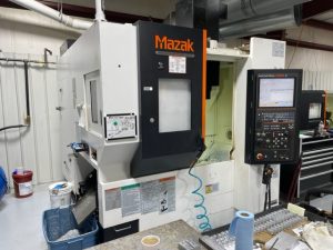
What is Auger-Style Chip Conveyor?
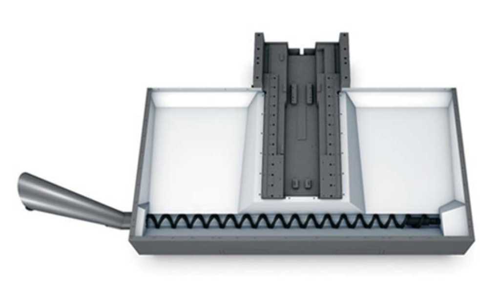
An auger-style chip conveyor, also known as a screw conveyor or flexible screw conveyor, is a mechanical material handling system designed to transport metal chips, swarf, and other machining debris generated during cutting operations. In the context of CNC (Computer Numerical Control) machine tools and machinery—such as lathes, mills, vertical machining centers (VMCs), and horizontal machining centers—this conveyor plays a critical role in chip management. It automates the removal of chips from the machining zone (e.g., the work envelope or coolant sump) to prevent accumulation, which could otherwise lead to tool breakage, poor surface finishes, thermal issues, or machine downtime. These systems are particularly suited for high-volume production environments where efficiency, coolant recycling, and operator safety are paramount.Unlike belt-based conveyors (e.g., hinge or scraper types), auger-style systems use a rotating helical screw mechanism, making them compact and ideal for integration into tight spaces within CNC enclosures. They are commonly employed in industries machining ferrous and non-ferrous metals, plastics, or composites, and can handle both wet (coolant-laden) and dry applications.Technical Principles and ComponentsThe core technology of an auger-style chip conveyor is based on the Archimedean screw principle, where a helical blade (the auger or screw flight) rotates within a cylindrical trough or tube to propel material forward via positive displacement. This design dates back to ancient engineering but has been adapted for modern CNC applications with materials like hardened steel or stainless steel for durability against abrasive chips.Key Components:
- Auger Screw:
- A continuous or sectional helical blade (flight) wound around a central shaft. The pitch (distance between flights), diameter (typically 50–150 mm for CNC applications), and flight thickness are engineered based on chip size, volume, and material density. For example, a finer pitch (e.g., 100–200 mm) is used for small, fine chips like those from aluminum milling, while a coarser pitch handles stringy chips from steel turning.
- The screw is driven by an electric motor (usually 0.5–2 kW, three-phase AC) coupled via a gearbox for torque multiplication, achieving rotational speeds of 20–100 RPM to balance transport efficiency and chip compression without excessive wear.
- In flexible auger variants, the screw is made from a coiled spring or wire-form material, allowing it to bend around curves or fit into irregular machine bases, which is advantageous for retrofitting into existing CNC setups.
- Enclosure (Trough or Tube):
- A U-shaped or tubular housing (often stainless steel or coated carbon steel for corrosion resistance in coolant environments) that contains the chips and prevents spillage. The enclosure is typically inclined at 10–45° to gravity-assist material flow, with lengths ranging from 1–5 meters depending on the machine size.
- Seals and bearings at both ends minimize coolant leakage and ingress of contaminants. For wet applications, the design includes provisions for coolant drainage ports to separate fluids from solids.
- Drive and Control System:
- Integrated with the CNC controller via M-codes (e.g., M31 for forward operation in Haas machines) or PLC (Programmable Logic Controller) interfaces. This allows automated cycling: the auger runs intermittently (e.g., 30–60 seconds every 5–10 minutes during machining cycles) to avoid constant operation and reduce energy use.
- Sensors (e.g., load cells or current monitors) detect jams, triggering reverse rotation (via M32 or similar) to clear blockages. Settings like conveyor on-time (e.g., Parameter 115 in Haas systems) and cycle interval (Parameter 114) fine-tune operation.
- Power requirements are low (typically 110–240V AC), and integration with high-pressure coolant systems ensures chips are flushed into the auger path.
- Discharge and Auxiliary Features:
- Chips are ejected at the end into a hopper, drum (e.g., 55-gallon barrel height of ~876 mm), or secondary conveyor (e.g., belt-type for further transport). In multi-auger setups (e.g., dual or quad configurations), side augers feed a central conveyor, enhancing throughput for large VMCs.
- Coolant wringing occurs naturally as the rotating screw compresses chips, reducing carryout (fluid loss) by 80–90% compared to manual removal. This supports coolant recycling, often paired with filtration systems like chip-disk filters (CDF) to prevent fines from entering the sump.
- Mobile variants include wheeled bases for portability, allowing one unit to service multiple machines.
Operational Mechanics:
- Material Transport: As the auger rotates, chips are captured between the flights and pushed axially along the trough. The volumetric flow rate ( Q ) can be approximated by the formula:Q=πD24×P×N×ρ×CQ = \frac{\pi D^2}{4} \times P \times N \times \rho \times C
Q = \frac{\pi D^2}{4} \times P \times N \times \rho \times Cwhere:- ( D ) = auger diameter (m),
- ( P ) = pitch (m),
- ( N ) = rotational speed (rev/s),
- ρ\rho
\rho= bulk density of chips (kg/m³, e.g., 500–1500 for metal swarf), - ( C ) = filling factor (0.2–0.4 for chips, accounting for voids).
- Chip Compression and Coolant Separation: The helical action compacts chips (reducing volume by 50–70%), squeezing out coolant, which drains back to the machine sump. This is crucial for maintaining coolant concentration and minimizing environmental disposal costs.
- Integration in CNC Machines: Installed in the machine base or foundation, the auger collects chips via gravity or washdown from the tool path. For lathes, a single axial auger runs along the bed; for mills, radial or side augers handle chips from the table. In high-production setups, it’s often the primary removal stage, feeding into belt conveyors for final discharge.
Advantages and Limitations in the CNC SectorAdvantages:
- Space Efficiency: Compact footprint (e.g., fits within 300–500 mm width), ideal for small-footprint CNCs like Haas VF-series or Brother mills.
- Versatility: Handles fine, stringy, or bulky chips from materials like steel, aluminum, or titanium; effective for both dry machining and flood coolant scenarios.
- Automation and Safety: Reduces manual intervention, lowering operator fatigue and injury risk (e.g., back strain from shoveling). Programmable operation minimizes machine stops.
- Cost-Effectiveness: Lower initial cost than belt systems (e.g., $2,000–$10,000 vs. $5,000–$20,000), with low maintenance (sealed bearings last 5,000–10,000 hours).
- Coolant Management: Minimal carryout promotes recycling, aligning with sustainability goals in modern CNC shops.
Limitations:
- Chip Type Sensitivity: Less effective for very long, stringy chips (e.g., from interrupted steel cuts), which can tangle and jam the screw—requiring reverse cycles or scraper add-ons. Fine aluminum chips may float and bypass if not paired with filtration.
- Capacity Constraints: Best for low-to-medium volumes (e.g., <10 kg/min); high-volume applications may need multi-auger or hybrid systems.
- Maintenance Needs: Abrasive chips accelerate wear on flights, necessitating periodic inspections. Not ideal for non-metallic or sticky debris without modifications.
- Installation: Requires precise alignment in the machine base, potentially increasing retrofit costs for older CNCs.
Applications in CNC Machine ToolsIn CNC lathes (e.g., Haas ST-series), auger conveyors remove chips from the spindle area to a rear discharge. For VMCs (e.g., Okuma or DMG Mori mills), dual/quad-auger systems with front conveyors manage chips from 3- or 5-axis operations, especially in automotive or aerospace part production. They integrate seamlessly with coolant tanks (e.g., 95–360 liters) and are often OEM options from manufacturers like Haas or aftermarket from suppliers like Hennig or LNS. For steel/stainless machining, augers outperform shovels by automating removal, though hinge-belt hybrids are preferred for heavy-duty setups.Overall, auger-style chip conveyors enhance CNC productivity by ensuring uninterrupted operation, with ROI achieved through reduced downtime (e.g., 20–50% less cleaning time) and coolant savings. For custom needs, consult manufacturers for simulations based on specific chip characteristics.