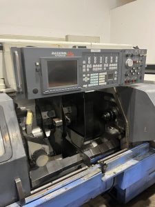

Technical Evaluation Guide: How to Identify a Quality Used, Secondhand, Pre-Owned, Surplus MORI SEIKI ZT-2500Y CNC Turning Center made in Japan
1. Reference / Baseline Specifications & What to Expect
Before your on-site inspection, secure the factory build sheet / as-delivered specification for that exact serial number of the ZT-2500Y. Use that to compare with what you see. Meanwhile, the following specifications from used listings give you a baseline “ballpark” reference:
From multiple sources:
- Spindle speed: 4,000 rpm
- Dual turrets, dual spindles, live tooling, Y axis
- Max turning diameter ~ 14.9 in / ~ 380 mm (for primary spindle)
- X-axis travel (turret 1): ~ 11 in (≈ 279 mm)
- X-axis travel (turret 2 / lower turret): ~ 7.9 in (≈ 200 mm)
- Z-axis travel (turret 1): ~ 37.8 in (≈ 960 mm)
- Z-axis travel (turret 2): ~ 38.8 in
- Y-axis travel: ± 2.8–2.9 in (≈ ± 70–75 mm)
- Maximum distance between spindles: ~ 51.2 in (≈ 1,300 mm)
- Turret tool capacities: 12 stations each turret (upper & lower)
- Rapid traverse (X / Z axes): 945 IPM (~ 24,000 mm/min)
These are approximate. If your candidate machine differs substantially (e.g. much lower spindle speed, fewer tool stations, smaller axes travel), ask for justification (variant model, component removal, etc.).
2. Documentation & History Review
Before you physically inspect, demand and review these documents. A machine with solid history is less risky to buy.
- Factory build / configuration sheet / drawing — includes details of spindles, turrets, live tooling, Y-axis, control version, options.
- Maintenance / service logs — chronological records of servicing (lubrication, spindle rebuilds, turret maintenance, drive / motor servicing).
- Operating hours / usage profile — total hours, hours under cutting load, percentage of idle vs production.
- Repair / overhaul history — any collision damage, turret repairs, spindle replacements, structural welds, control upgrades.
- Calibration / alignment / metrology reports — e.g. straightness, axis alignment, backlash reports, return-to-zero tests.
- Tooling & accessories records — what tooling, live tool holders, sub-spindle attachments, collets, fixtures are included.
- Spare parts inventory — especially crucial parts (bearings, seals, encoder modules, turret parts, etc.).
- Control / CNC backups — parameter files, error logs, alarm history, control interface manuals.
If documentation is sparse or inconsistent, your inspection must be more exhaustive, and you should demand more warranty or discount.
3. Visual / Structural / Cold Inspection
With power off, inspect the machine’s external structure, mechanical systems, and wear indicators.
Base, Bed & Structure
- Inspect machine base, bed, cross members, castings for cracks, weld repairs, distortions, misalignment.
- Check for surface corrosion, pitting, rust especially in hidden areas or corners.
- Verify structural joints, stiffeners, mounting flanges are clean, tight, and undistorted.
- Check for missing or damaged covers, guards, splash panels, enclosures.
Guideways, Turret Slides, Carriages
- Examine linear guide surfaces on X, Y, Z axes, turret slides: look for scratches, scoring, pitting, uneven wear.
- Check wipers / bellows / protective covers: if damaged, contamination may have entered internal components.
- Inspect turret slide rails, turret bearing surfaces for signs of wear, play, or misalignment.
Spindles & Spindle Noses
- Examine both main and sub-spindle nose / taper surfaces: look for pitting, corrosion, dents, discoloration.
- Check for evidence of past repairs, alignment marks, or tampering.
- Inspect spindle housings, bearing covers, seal areas for leakage, corrosion.
Turrets, Tool Pockets, Live Tool Assemblies
- Inspect both turrets: turret indexing surfaces, pocket seats, pockets, cam surfaces, grippers.
- Look for worn or damaged turret pockets, misalignment, cracks, or mechanical play.
- Inspect live tool drive heads (if present): check wiring, connectors, bearings, housing condition.
Y-Axis / Cross Slide / Upper Turret Support
- Inspect Y-axis components (upper turret Y slide) for wear, binding, misalignment.
- Check for play or looseness in support structures for Y-axis motion.
Fasteners, Access Panels, Wiring
- Check structural bolts, large connecting bolts: none missing or deformed.
- Open access panels: wiring should appear neat, no obvious overheating, burnt insulation, broken connectors.
- Inspect cable carriers, conduit routing, hoses for wear, chafing, slack, or damage.
Lubrication, Coolant, Chip Handling
- Examine lubrication lines: regulators, pressure gauges, flow lines, distribution to axes.
- Check coolant piping, nozzles, hoses, pump housing for leakage, corrosion.
- Inspect chip conveyors / chip removal system (if present) for wear, damage, alignment.
4. Static / Mechanical / Kinematic Checks (Manual / Slow Mode)
If safe and permitted, actuate axes in manual or jog mode to sense mechanical behavior, backlash, binding, and alignment issues.
Axis Motion (X, Y, Z)
- Jog or manually move each axis slowly through portions of travel: feel for smoothness, binding, grit, jumps.
- Reverse direction and measure backlash / lost motion with a dial indicator (e.g. ± a small offset and back).
- At different points of the travel, use a test indicator to verify straightness of motion (e.g. slide along rail, check deviation).
Turret Indexing
- Manually index each turret through all pocket positions (in slow or manual mode). Observe for hesitation, misindexing, binding.
- Test turret locking: when turret locks, there must be minimal residual play.
Spindle / Toolholder Play (Static)
- Mount a known, good, clean toolholder / test bar. Gently twist or tap to see if any radial or axial play is present.
- Use a dial indicator to measure runout at tool tip or taper area.
- Use a marking compound (dye contact test) on taper seating: seat the toolholder gently, rotate, remove, and inspect contact patch. Uniform contact is needed; partial / uneven contact implies wear.
Y-Axis / Cross Slide (Static)
- Jog or move the Y-axis of upper turret (if equipped) to check smoothness, binding.
- Reverse direction and check backlash in Y-axis.
- Check for play or looseness in Y-axis guide / support structure.
Drive / Gear / Coupling Checks
- If safe, move or rotate drive elements (gearboxes, couplings) by hand to feel for roughness, binding, looseness.
- Listen or feel for rough spots, detents, or binding in coupling joints.
Tool Changer / Tool Load / Retract (if present)
- Manually actuate tool change sequence (if possible) or jog components: check for smooth operation, correct travel, no collisions or misalignments.
5. Power-On / Dynamic / Functional Testing
With machine powered in a safe environment, test all dynamic functions under motion and (if allowed) light cutting.
Control / CNC & Interface
- Power on the CNC: observe initialization, alarms / fault history, parameter load, axis enable states.
- Test operator interface: jog commands, incremental moves, coordinate display, overrides.
- Run homing / reference cycles for all axes and verify consistent referencing.
- Execute a purely motion program (no cutting) combining multiple axes (X, Y, Z, turret moves) to validate smoothness and absence of interference or stub collisions.
- Test safety circuits: limit switches, interlocks, emergency stop, door guards.
Axis Motion Under Load
- Command box or ladder moves (X / Z / Y combinations) while monitoring via external indicator or displacement sensor to verify repeatability, accuracy, and smooth motion.
- Run return-to-zero sequences and note deviation.
- Test acceleration / deceleration behavior: spot overshoot, jerk, stalling, or instability.
Spindle / Turning & Live Tool Cutting (Light Load)
- Ramp spindle(s) up through speeds (low → up to 4,000 rpm) if possible. Listen for bearing noise, vibration, smooth acceleration.
- Perform a light turning cut on a soft material (e.g. aluminum) to test actual cutting behavior: monitor surface finish, absence of chatter, consistent load.
- If live tooling is functional, run a light milling pass or tool operation to test live tooling axes (rotational stability, chatter, tool drive behavior).
- Monitor motor currents, servo behavior, tool engagement, and spindle stability.
Turret / Tool Change Dynamic Test
- Run tool change cycles via CNC: turret indexing, tool load / unload, tool clamping. Watch for hesitation, misalignment, missed picks, or collisions.
- After multiple tool changes, check if tool offsets / lengths remain stable (i.e. minimal drift).
- Check whether the system recovers position reliably post-tool change.
Y-Axis / Multi-Axis Functionality
- If the machine has Y-axis capability on upper turret, command motions in Y while machining or positioning and monitor behavior, smoothness, interference, and repeatability.
- Combine turret movement + Y + other axes to test multi-axis coordination.
Warm-Up / Thermal Drift Test
- Let the machine run (spindle on, axes moving) for a sustained period (30–60 min). Then re-check critical reference moves or test cuts to evaluate drift or geometry change.
- Monitor servo motor / drive temperatures, axis temperature gradients, spindle bearing temperature.
6. Metrology / Accuracy & Precision Verification
To certify quality, perform measurement tests using precision instruments to validate geometric integrity and performance.
- Straightness / linearity over the travel of X, Z axes: measure deviation vs ideal straight path.
- Squareness / perpendicularity: between axes (X–Z, X–Y, Z–Y) to check whether coordinate system remains orthogonal.
- Backlash / reversal error measurement in axes (X, Y, Z) through multiple small offset tests.
- Spindle runout / taper alignment: mount a precision test bar and check radial and axial runout, verify taper centering.
- Tool change repeatability: after tool changes, measure tool tip offsets to evaluate drift or error.
- Thermal drift repeatability: compare measured offsets before and after warm-up period.
- Live tooling accuracy (if used): measure machining of known features to see live tool precision.
- Multi-axis consistent performance: ensure that combined axis movements produce accurate and repeatable paths.
Compare measured values to the original factory tolerances (if available) or to your required production tolerances. Slight deviation is acceptable; large, erratic deviations are not.
7. Key Red Flags & Warning Signs
During your inspection and testing, the following conditions are serious warning indicators. If you observe any of these, you must demand clarification, repairs, or even walk away.
- Excessive or inconsistent backlash / slop in X, Y, Z axes, turret indexing, or live tooling axes.
- Binding, stick-slip, or “dead zones” in axis motion.
- Spindle bearing noise, vibration, or play (static or under motion).
- Uneven taper contact or a bad dye test on toolholder taper surfaces.
- Tool change failure, misindexing, tool drops, collisions, incomplete clamping.
- Y-axis motion that is jerky, misaligned, or drifts during operation.
- Turret pocket wear, misaligned pockets, cam damage, or clutch slippage.
- Poor repeatability in return-to-zero or repeated moves.
- High thermal drift (geometry shifting substantially during warm-up).
- Missing or damaged covers, wipers, guides, protective bellows, which allow contamination ingress.
- Evidence of structural repair (welding, cracks, patches) on critical parts (bed, turret housing, spindle housing).
- Control / CNC errors, axis disable faults, parameter memory corruption.
- Overheated / worn motors or drives (smell, heat, discoloration).
- Lack of or suspect maintenance history; missing critical spares.
- Obsolete or no longer supported control modules / parts (especially for dual spindle / turret systems).
If multiple red flags exist, the machine’s risk is high, unless the seller addresses them or discounts heavily.
8. Refurbishment / Risk Buffer & Cost Estimate
Even a “good” used ZT-2500Y often requires refresh / service. When planning your offer, budget for:
- Spindle bearing replacement or repair
- Regrinding or refurbishing guideways, slides, turret cam surfaces
- Replacement of ball screws, nuts, encoders or drive elements
- Turret overhaul (cams, clutches, grippers)
- Live tooling head refurbishment / spindle repair
- Y-axis stabilization or rebuilding
- Control / drive / servo electronics overhaul or replacement
- Re-lubrication, cleaning, cover / bellows replacement
- Calibration, alignment, metrology verification, test cuts
- Installation, leveling, commissioning, training
- Contingency margin (10–20 % or more) for hidden problems
9. Contract / Acceptance Safeguards & Test Protocols
To protect your investment, include the following in your purchase agreement:
- On-site test / “burn-in” clause: allow you to run the machine under real conditions (turning + live tooling) after installation before final acceptance.
- Acceptance criteria / tolerance schedule: define allowable limits for backlash, runout, repeatability, thermal drift, live tooling error.
- Test part / sample program run: bring your own test materials and part geometry so you can validate machine capability.
- Independent inspection clause: allow a third-party metrology / machine-tool specialist to audit performance before final acceptance.
- Warranty / guarantee period: especially for critical subsystems (spindles, turrets, live tooling, Y-axis) for a defined period.
- Holdback / retention clause: retain part of payment until acceptance is confirmed.
- Disclosure clause: seller must disclose known defects, repairs, or limitations.