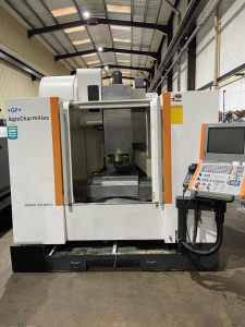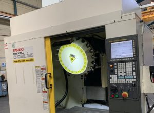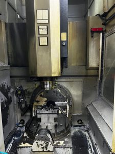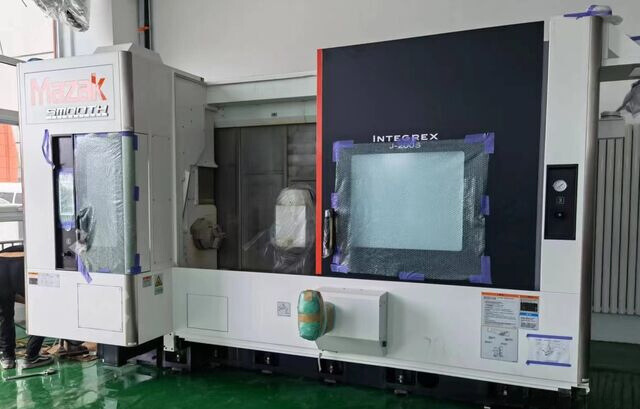
Technical Evaluation Guide: How to Identify a Quality Used, Secondhand, Pre-Owned, Surplus MAZAK INTEGREX J-200S CNC MultiTasking Turn-Mill Center Machine made in Japan
1) Machine Overview & Baseline Specs
Before visiting the machine, get the factory spec sheet for that particular J-200S. Here are representative specs and features to use as benchmarks:
| Feature | Published Spec / Note |
|---|---|
| Chuck size (main & second spindle) | 8″ (for J-200S) |
| Maximum machining diameter | Ø 500 mm (≈ 19.69″) on many J-200 models |
| Maximum machining length | ~ 910 mm (for certain bed versions) |
| Spindle speed (main / secondary) | Up to 5,000 rpm (main & second) |
| Milling (B-axis / turret) spindle | Up to 12,000 rpm option |
| X / Y / Z travel | Example: X = 450 mm, Y = 200 mm, Z = 1,119 mm (for one variant) |
| Y-axis travel | 200 mm for many units |
| Tool magazine | 20 tools standard (can be larger) |
| B-axis indexing capability | -30° to ~190° (5° increments standard) |
| Second spindle | Integral motor spindle for secondary turning |
These provide “expected range” values. During inspection, deviations from these must be evaluated carefully — some differences may arise from optional configurations or retrofits.
2) Document Request Before Inspection
Ask the seller to provide:
- Machine serial number, build year, model variant (J-200S vs J-200)
- Full factory configuration / build sheet (spindle sizes, B-axis option, Y-axis stroke, tool magazine size)
- Maintenance logs: spindle rebuilds, axis overhauls, clamp / hydraulic service
- Geometry / calibration / laser / ballbar test reports
- CNC parameter backups, axis compensation & offset tables
- Electrical / hydraulic / pneumatic schematics
- Tooling list (milling cutters, driven tools, holders)
- Any retrofit or modification records
- Alarm history logs and copies of major error events
These documents help you interpret which deviations are within tolerance and which are indicative of serious wear or damage.
3) Static & Visual Inspection (Power Off)
Begin by walking around the machine and inspecting major components before powering:
- Frame, base & castings: Look for cracks, evidence of repair welding, corrosion, or distortion.
- Way covers / bellows / guards: Check for tears, missing covers, chip intrusion, hardened sludge.
- Spindle noses / taper surfaces: Inspect for surface wear, corrosion, scratches, or seating problems.
- Turret / B-axis head housing: Inspect for cracks, misalignment, welds, or signs of stress.
- Guideways & linear rails: Check for scoring, pitting, uneven lubrication traces, dark patches (wear).
- Tool magazine & ATC components: Inspect magazine body, gripper arms, indexing faces for loosening or play.
- Cable chains / hoses / plumbing: Look for brittle insulation, smashed hoses, past repairs.
- Electrical cabinet & internal wiring: Open and observe if wiring is tidy, terminals not overheated, power supplies clean.
- Safety doors / interlocks / covers: Ensure doors fit well, interlocks work, hinges not sagging.
Record photographic evidence of any visible damage or suspicious wear.
4) Installation / Alignment Checks
If the machine is already semi-installed or on supports:
- Check machine base level and anchor bolts—imperfect leveling can mask geometry issues.
- Use a calibration bar / test spindle to check radial runout of the main spindle in neutral B-axis position.
- Command small movements in X, Y, Z to verify smooth travel and absence of binding or unusual resistance.
- Mount a dial indicator on turret face relative to spindle axis; index B-axis head / turret and see deviation.
- If accessible, tilt B-axis slightly and check whether spindle remains aligned to turret / tool paths (no noticeable tilt drift).
5) Power-Up & Functional Tests
After ensuring safety and power availability, run dynamic tests:
- Warm-up / jogging: Jog axes (X, Y, Z, B, C) continuously for 20–30 minutes to stabilize thermal conditions.
- Homing / reference return: Check that the machine homes consistently and repeatably, without limit- or reference errors.
- Axis stroke test: Move X, Y, Z axes through full travel at varying speeds (25 %, 50 %, 100 %), listening carefully for harsh spots or chatter.
- B-axis / milling head motion: Index B-axis across its full range repeatedly. Check for binding, torque irregularities, or hesitation.
- Second spindle test: If the unit is a J-200S, run the second spindle up to speed (e.g. 5,000 rpm) and test direction, no-load vibration.
- Spindle ramp-up: Gradually accelerate the main spindle through its RPM range, monitor vibration, sound, current draw, and temperature trend.
- Tool change cycles: Cycle magazine or ATC multiple times, check repeatability, gripper function, tool pick/drop success.
- Milling spindle (if equipped): Run milling spindle at various speeds under minimal load and check for smoothness, reaction, noise.
- Coolant / lubrication systems: Engage coolant pumps, check flow, pressure, for leaks. Turn on lubrication supply and confirm oil / grease to axes.
- Control / alarms check: Monitor for servo or axis alarms, limit trips, parameter errors; review alarm log history.
- Cable / sensor feedback: While motioning, verify encoder feedback is stable, no dropouts or error messages.
6) Accuracy, Repeatability & Metrology Tests
These separate a high-performing used unit from a mediocre one:
- Linear positioning / straightness tests: Use a laser interferometer or calibrated displacement device on X, Y, Z axes and compare commanded vs actual positions.
- Backlash / reversal error: Execute small ±0.01 mm moves in axes and measure the difference on direction reversal.
- Repeatability: Return to the same point multiple times (e.g. 10×) and measure deviation.
- B-axis indexing repeatability: Index B-axis repeatedly and measure angular deviation.
- Combined interpolation / contour test: Command a combined motion (turning + milling) and measure how closely the machine achieves the intended path.
- Thermal drift check: Run under load for 1–2 hours, then re-measure reference features to detect dimensional drift.
- Hysteresis: Move to a position, dwell, return, and measure offset from original.
- Turret / tool location consistency: Measure repeatability of tool placement via turret indexing.
7) Spindle, Tooling & Wear Checks
- Spindle runout & vibration: Mount a test bar and measure radial runout, plus optionally use vibration analysis to detect bearing defects.
- Spindle noise: Listen for whine, growl, or bearing hum at intermediate RPMs.
- Temperature rise: Run spindle under moderate rpm/stall conditions for ~30 min and monitor temperature increase.
- Tool retention / drawbar test: If drawbar or tool retention device is present, measure retention force or torque.
- Taper contact inspection: Use blue-dye or surface contact test to see if taper seating is even.
- Tool change repeatability: Execute multiple tool changes and verify that tool offsets return within tight tolerances.
- Milling spindle bearing & smoothness: If the milling spindle is built-in, accelerate and monitor for vibration or runout.
8) Lubrication, Cooling & Auxiliary Systems
- Coolant system: Flow, pressure, clarity, leaks. Check filters, residue, plumbing for signs of blockage or corrosion.
- Lubrication / grease / oil system: Ensure lube lines to all axes / turrets / B-axis are active, and check for clogged lines or missing supply.
- Chip handling / conveyor / removal: Operate chip conveyor or removal system to confirm free movement, no jam.
- Hydraulic / pneumatic systems (if any): Test pressure, valve responsiveness, check for leaks, stability.
- Filtration & coolant return: Evaluate condition of filters, screens, and tramp-oil / coolant cleanliness.
- Cabinet ventilation / cooling: Verify fans and heat exchangers work, no high temperature in drive cabinet.
9) Wear Patterns & Common Failure Modes to Watch
- Wear or scoring on guideways, especially on axes with heavy load (likely Y or Z).
- B-axis bearing or indexing coupling wear — angular inconsistency or “play.”
- Turret / tool magazine wear or play, loose indexing or wobble.
- Spindle bearing fatigue, especially in the main spindle or second spindle.
- Tool change or tool retention slippage or deviation.
- Loss of lubrication to moving parts (blocked lines, dry spots).
- Coolant leaks or contamination causing internal corrosion.
- Servo drive / control board aging — repeated alarm history, drive temperature issues, capacitor bulging.
- Encoder feedback issues — intermittent errors or dropouts on axis motion.
10) Acceptance Criteria / Target Tolerances (Benchmarks)
Use this as your “go/no-go” checklist (adjust per the spec sheet and intended precision):
| Parameter | Target / Acceptable Tolerance |
|---|---|
| Linear positioning accuracy (X, Y, Z) | ± 0.005 mm over moderate stroke |
| Backlash / reversal error | ≤ 0.01 mm |
| Repeatability over cycles | ≤ 0.005 mm |
| B-axis / indexing repeatability | ≤ 5 arc seconds (if spec allows) |
| Spindle radial runout | ≤ 0.005 mm |
| Thermal drift over 1 hr | ≤ 5 µm |
| Tool change / offset repeatability | ≤ 0.01 mm |
| Control servo load stability | Smooth currents, no spikes |
| Coolant & lubrication stability | No significant drops or pressure fluctuations |
| Noise / vibration at rpm | Minimal, no bearing whine |
If the machine fails multiple criteria, you should negotiate accordingly or walk away.
11) Red Flags / Walk-Away Conditions
- B-axis or turret mis-indexing, errors, or mechanical play
- Spindle vibration, noise, or high runout at any speed
- Repeated servo / axis errors or alarm codes in log history
- Tool change failures, gripper slippage, magazine misalignment
- Loss of coolant pressure, leaks inside machine structure
- Worn guideways or visible scoring in critical travel zones
- Missing or corrupt CNC backups / parameter memory
- Control / drive overheating, smells, or burnt wiring
- No maintenance or calibration history, or undocumented modification
12) Buyer’s On-Site Quick Checklist
- Confirm serial number, model variant, and spec sheet
- Review maintenance & calibration records
- Visual inspection of frame, guards, cover, ways
- Jog X, Y, Z, B axes; listen and feel for anomalies
- Index B-axis / turret repeatedly
- Ramp spindle and test runout / vibration
- Accuracy / repeatability / drift tests
- Coolant, lubrication, and chip systems operational
- Review control boot-up, alarm logs, backups
- Walk away if multiple serious defects present