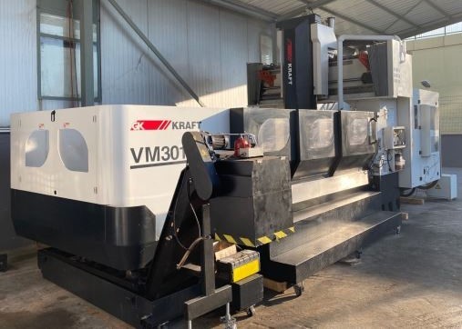
Technical Buyer’s Handbook: Assessing Pre-Owned , Used , Secondhand, Surplus CNC Machines Before Purchase Kraft VM3018A CNC Vertical Machining Center Double Column 5 Axes
Below is a Technical Buyer’s / Due-Diligence Handbook / Inspection Checklist tailored for evaluating a pre-owned / used / surplus KRAFT VM3018A (Double Column / Planer-type / large CNC milling / gantry style machine). Use this as a structured guide; you’ll need to adapt tolerances, priorities, and weighting to your shop’s part size, accuracy requirements, and maintenance capability.
I. Reference / Benchmark Specifications (KRAFT VM3018A)
Before arriving, assemble the nominal / expected specs (or the seller’s spec sheet) for comparison. From the listing we saw:
| Parameter | Quoted / Typical Value |
|---|---|
| X-travel | 3,200 mm |
| Y-travel | 2,000 mm |
| Z-travel | 1,000 mm |
| Distance spindle nose to table | 200–1,200 mm |
| Distance between columns | 1,820 mm |
| Table size | 3,200 × 1,600 mm |
| Table load capacity | 10 tons |
| Spindle taper / nose | BT 50 |
| Spindle speed (direct drive) | 6,000 rpm |
| Spindle motor power | 22 kW |
| Rapid traverse (X/Y/Z) | 20 / 20 / 12 m/min |
| Positioning accuracy | 0.025 mm |
| Repeatability | 0.02 mm |
| Total power requirement | 60 kVA |
| Approximate weight | 26 tons |
| Footprint / dimensions | ~ 8,927 mm length × 5,535 mm width × 4,650 mm height |
These serve as a baseline. If the unit you’re evaluating deviates significantly (e.g. much slower spindle, reduced travel, lower load rating), you’ll need to understand why (wear, modifications, motor downgrade) and factor the risk.
II. Pre-Inspection / Remote Preparation
Before going to inspect on-site, do as much preparation as possible:
- Request documentation
- Manufacturer’s mechanical, electrical, hydraulic (if any) manuals
- Wiring diagrams, control wiring / I/O drawings, axis drive schematics
- CNC / controller parameter backups (e.g. offsets, compensation tables)
- Maintenance / service logs: breakdowns, part replacements (spindles, linear guides, screws)
- Calibration / alignment / geometric measurement reports
- Modification / retrofit records (e.g. controller upgrade, spindle changes)
- Spare parts / BOM list - Obtain photos & videos
Ask the seller for high-resolution images or short video clips showing:
- Entire machine (front / back / side)
- Table surface and underside
- Linear guides, column faces, reference surfaces
- Spindle head and nose, tool change area
- Control cabinet interior, wiring, drive modules
- Motion videos (X, Y, Z axis jogging, spindle run) if machine is operational - Ask key clarifying questions
- Year of manufacture, serial number
- Total running hours / duty cycle
- Usage profile (type of parts, loads)
- Reason for sale / decommission
- Known defects, accident history, repairs
- Is the machine currently operational / powered?
- What spare parts / tooling / fixtures are included
- Which controller (Fanuc, Siemens, etc) and version - Bring inspection / measurement tools
- Dial indicators, test bars, micrometers, straight edges
- Laser alignment tools (if available)
- Vibration sensor / accelerometer
- Thermography / infrared camera
- Torque wrenches, feeler gauges
- Tools for opening panels, measuring wiring continuity, etc - Check logistics & facility constraints
- Weight and rigging / crane access, lifting points
- Foundation / floor bearing capacity, flatness
- Power supply, voltage, phase, capacity
- Cooling, ventilation, exhaust, auxiliary services
- Room / clearance for movement, service, and access
III. Visual & Structural / Static Inspection (Power-Off)
Once on-site, before powering, perform a thorough structural and mechanical inspection.
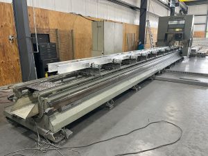
3.1 Frame, Columns & Base
- Inspect base, bed, columns, cross beams for cracks, weld repairs, distortion, bending
- Look for signs of rework, leveling shims or alignment repairs
- Check for corrosion, pitting, surface degradation in coolant / chip areas
- Inspect covers, guarding, way covers, bellows, seals for damage or missing parts
- Use a straight edge to spot obvious large-scale twist or misalignment
3.2 Linear Guides, Rails, Carriages, Ball Screws
- Inspect guide rails / ways for scoring, nicks, wear, spalling
- Check carriages for play, looseness, side movement
- Examine ball screws or drive screws / nuts for backlash, wear, pitting
- If possible, manually slide axes (light push) to sense binding, stick-slip behavior
- Check lubrication system: oil / grease lines, fittings, blockages, leaks
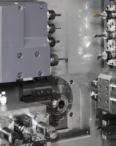
3.3 Spindle Head, Nose, Tool Interface
- Inspect the spindle nose / taper / clamping surfaces for wear, damage, burrs
- Check spindle head housing, bearings, seals for leakage, discoloration
- If possible, insert a test bar (without spinning) to measure static run-out
- Inspect cooling / lubrication lines to spindle, check for leakage or blockage
3.4 Tool Changer, Magazine (if applicable)
- Inspect tool changer arms, grippers, slides, indexing mechanisms for wear, slack
- Check sensors, mechanical limit switches, wiring, actuator hardware
- Inspect magazine pockets and interface alignment
3.5 Electrical Cabinets & Drive Hardware
- Open control / drive cabinets (if allowed) and inspect wiring, terminal blocks, connectors
- Look for signs of overheating: discolored wires, melted insulation, corrosion
- Check drive modules, power modules, control boards for obvious damage or dust buildup
- Inspect cooling fans, filters, ventilation pathways
- Inspect cable carriers / drag chains for damage / abrasion
3.6 Safety Systems & Interlocks
- Confirm presence and mechanical integrity of emergency stop (E-stop) buttons
- Inspect guard doors, interlock switches, safety covers
- Verify that safety circuits are not bypassed
- Check limit / home switches for axes
IV. Power-Up & Functional / Dynamic Testing
Once static checks pass (or are acceptable with caveats) and safety is assured, proceed with controlled power-up and dynamic tests.
4.1 Control & Diagnostic Check
- Power on the CNC / control; observe boot, error messages, alarms
- Verify that CNC parameters, offsets, compensation tables load correctly
- Check I/O input states: limit/home switches, safety interlocks, sensors
- Jog axes at low speed; confirm correct direction, smooth motion, no binding
4.2 Homing / Referencing / Return-to-Zero
- Execute homing / referencing cycles on X, Y, Z axes
- Repeat homing multiple times to test repeatability of reference position
- Test limit switches / soft limits to see if axes stop or retract properly
4.3 Axis Travel & Motion Behavior
- Traverse axes across full available travel (within safe limits); watch for jerk, binding, vibrations
- Command known distance moves (e.g. 100 mm, 200 mm) and measure with a dial gauge or reference
- Reverse direction and check for backlash / dead-zone
- Execute simultaneous multi-axis moves (e.g. diagonal) to test coordination, if control supports
4.4 Spindle / Rotation Test
- Start spindle at low RPM; observe behavior, noises, vibration
- Ramp up to higher rpm (within spec) and monitor stability
- If possible, measure dynamic run-out with a test bar during rotation
- Monitor spindle motor current and temperature
- Confirm spindle cooling / lubrication works under motion
4.5 Tool Change / ATC (if present) Test
- Execute multiple tool changes; observe timing, sensor detection, indexing accuracy
- Cycle tool changes many times to test reliability and repeatability
- Try changes with different tool sizes / weights (within safe limits)
4.6 Test Cut / Machining Simulation (if allowed)
- Run a light machining test on a soft material (e.g. aluminum)
- Compare part geometry vs programmed geometry, inspect surface finish
- Let the machine run for some time (30–60 min) to observe drift, thermal effects
- Monitor power draw, vibration, deviations over time
4.7 Safety / Fault Behavior Tests
- Press E-stop during axis motion or spindle run; machine must stop safely
- Trigger limit switches or home switches to test safe behavior
- Simulate sensor failures (if safe) to see how control handles errors
- Open guards or safety doors during motion (if system supports) to see if inhibition / interlock works
4.8 Stability / Endurance / Thermal Testing
- Run repeated cycles or idle operation for long duration (30–60 min) to let temperature stabilize
- After warm-up, re-check key positioning, backlash, repeatability to detect shift
- Monitor drive / motor / control cabinet temperatures
- Use thermography or vibration analysis to find hot spots or developing issues
V. Precision, Calibration & Accuracy Testing
Once the machine is thermally stable, conduct precision tests to assess whether performance meets your tolerances.
- Repeatability test: move to a point, retract, return, measure deviation
- Grid / mesh test: command an array of positions (X–Y) and measure resulting positional errors
- Squareness / orthogonality check: move in X then Y and Y then X, compare positional differences
- Spindle alignment / overlay: test whether spindle center line aligns with axes over travel
- Under load or offset part positions, observe whether deflection or deviation occurs
- If you have high-precision tools (laser interferometer, alignment fixtures), use them for error mapping
- Compare measured deviations vs acceptable tolerances (based on application or machine specs)
VI. Documentation & Maintenance History Review
Once mechanical and dynamic tests are done, review the documentation and service history carefully.
- Service / maintenance logs: major repairs, overhauls (spindle, guides, drive modules)
- Calibration / alignment / compensation reports
- Upgrade / refurbishment records
- CNC / controller software / version history, backups
- Spare parts inventory included (bearings, screws, electrical modules)
- Tooling, fixtures, accessories supplied
VII. Risk Assessment, Life-Remaining Estimate & Cost Projection
Using your inspection and test data, build a risk / cost forecast model.
- Wear-critical subsystems: linear guides, ball screws, spindle bearings, tool changer
- Spare part availability / cost: for KRAFT or OEM parts, electrical modules, drive units
- Calibration / re-adjustment cost post relocation / installation
- Transport / installation risk (misalignment, shock, packaging damage)
- Commissioning / ramp-up downtime cost
- Control / electronics obsolescence: drive boards, controller modules aging
- Fallback / salvage value: structural parts, frames, non-wear components
You may assign weights to subsystems (structure, axes, spindle, control, tooling) to derive a condition score that guides your maximum acceptable price or repair buffer.
VIII. Contractual Safeguards & Negotiation Clauses
Use your due diligence to negotiate protections in the purchase agreement.
- Acceptance / test clause: tie final acceptance to passing performance tests after installation
- Price adjustment clause: allow deductions if key metrics deviate from agreed tolerances
- Warranty / latent defect clause: e.g. 3–6 months on hidden failures (e.g. spindle, drives)
- Spare parts package: require inclusion of critical wear parts (bearings, screws, seals, electrical modules)
- Documentation handover guarantee: all manuals, wiring, parameter backups, calibration records
- Transport / insurance clause: specifically assign responsibility for damage during transit / unloading
- Installation / commissioning support clause: seller or OEM technician support first alignment / calibration
IX. Post-Purchase / Installation & Commissioning Checklist
Once the machine is delivered and installed in your facility, follow a careful commissioning process:
- Prepare and level the foundation, anchor points, vibration isolation
- Clean, flush, and refill lubrication / coolant systems; replace filters as needed
- Reconnect and verify wiring, grounding, and safety systems
- Power up and repeat the acceptance / functional / precision test suite
- Perform alignment, geometry calibration, compensation (straightness, squareness, backlash)
- Run test parts using your materials to confirm real-world performance
- Capture baseline metrics (repeatability, drift, backlash)
- Train operators & maintenance staff on machine idiosyncrasies
- Establish preventive maintenance schedule (e.g. periodic alignment checks, lubrication audits)
- Monitor performance in early weeks: drift, alarms, deviations