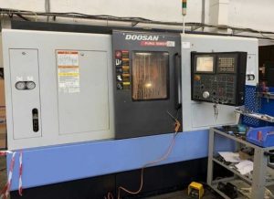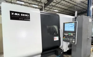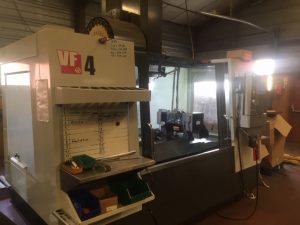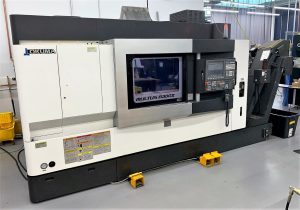
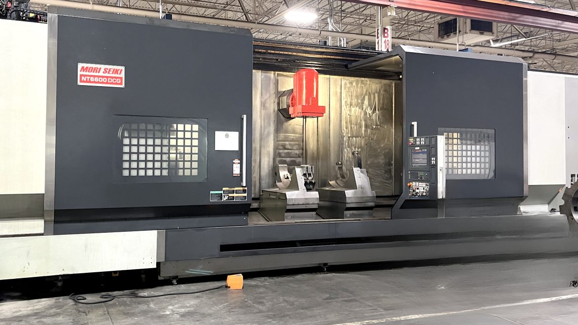
Smart Buyer’s Guide: How to Choose the Right Pre-Owned, Used, Secondhand, Surplus CNC Equipment Before Purchasing Mori Seiki NT6600DCG/4000CS CNC Multi-Tasking Turn-Mill Center made in Japan
If you’re considering acquiring a pre-owned / used / surplus Mori Seiki NT6600DCG / 4000CS (or equivalent NT-series turn-mill / multi-tasking center), the stakes are high. These machines are complex and expensive, so mistakes in selection can be very costly. Below is a Smart Buyer’s Guide to help you systematically evaluate, mitigate risk, and make an informed purchase. (I’ll also point out what’s special about the NT6600DCG line.)
1. Understand the Machine’s “Born” Specifications & Features
Before you inspect, you must know the design envelope, what features are optional, and what normal wear looks like. For the NT6600DCG series (and variants), here are some baseline specs and features you should verify against the seller’s claims.
Key Specifications & Special Features (NT6600DCG Line)
Some of these are drawn from Mori / DMG MORI product data.
| Parameter | Typical / Published Value | Notes & Variants to Watch |
|---|---|---|
| Max turning diameter | φ 1,070 mm (≈ 42.1 in) | Over bed / over cross depending on configuration |
| Max workpiece length | Up to ~ 6,076 mm (≈ 239 in) | Variants: “3000”, “4000”, “6000” versions with shorter or longer Z travel |
| Axis travels (X / Y / Z) | X ≈ 1,040 mm, Y ≈ 660 mm, Z ≈ up to ≈ 6,150 mm | The seller variant (e.g. “4000CS”) may have shorter Z travel |
| Bar / spindle bore / spindle specs | Bar capacity ~ 164 mm (6.5 in) Spindle speeds for main and milling spindles in various variants (e.g. 8,000 rpm for milling) | Check which spindle / motor option the machine has (C8, BT50, etc.) |
| Control / software system | MAPPS / Mori controls (CELOS, MAPPS IV etc.) | Some used machines may have aftermarket control retrofits |
| Special rigidities & thermal controls | The NT6600DCG employs Mori’s “DCG” (Driven at the Center of Gravity) design, “ORC” octagonal ram structure, and direct-drive axes to reduce vibration, backlash, and thermal displacement. | These features are what distinguish a well-functioning NTDCG from lesser variants |
| Tooling, live tooling, B / C axes | Multi-tool, B-axis rotation (±120° typical) & potentially full 5-axis capability in certain variants. | If the machine you evaluate lacks or has degraded those subsystems, it’s a significant downgrade |
| Steady rests, tailstock, dual spindles | The machine may support 1 or more steady rests, optional second spindle (in some variants) | Be clear which options your specific candidate includes |
| Mass / footprint / power / cooling | Very heavy (tens of tons), large footprint, extensive power and cooling needs | You must ensure your facility can handle it |
Knowing these as reference values lets you spot undervaluation, exaggeration, or missing features in the used machine.
2. Pre-Inspection Information & Documentation to Request
Before you or your inspection team set foot on the shop floor, gather as much of the following as possible from the seller:
- Serial number(s), build year(s), model code / variant (e.g. “4000CS”, “3000”, etc.)
- Complete service and maintenance log: major repairs, spindle rebuilds, axis rebuilds, control upgrades
- Hours of operation (spindle hours, cutting hours, “machining hours” if tracked)
- A list of all modifications, retrofits, or non-factory changes (e.g. non-original controls, added auxiliary systems)
- Copies of mechanical, electrical, hydraulic, pneumatic, wiring diagrams, and parts list / BOMs
- Copies of CNC / control program backups, parameter backups, software / firmware version / licensing
- List of all included tooling, fixtures, steady rests, chucks, collets, tailstock, etc.
- Spare parts included or offered, and a parts availability report (which major spares might be obsolete)
- Pictures and videos of the machine (especially in motion: axes moving, spindle running, tool changes)
- Any records of alignment or calibration, remanufacture, or rebuilds done
Having this data ahead of the inspection reduces surprises, lets you prepare measurement tools, and gives you negotiating leverage if the documentation is incomplete or conflicting.
3. On-Site / In-Person Inspection & Measurement Checklist
Once you are physically present, you must dissect the mechanical, electrical, and functional state of the machine. The following checklist is somewhat detailed but suited to a machine of this complexity.
A. Mechanical / Structural & Wear Inspection
- Frame, bed, saddle, casting integrity
- Check for cracks, weld repairs, distortions, or signs of fatigue, especially near heavily loaded areas.
- Ensure the base is level and straight; no sagging or chassis deformation.
- Inspect all cover plates, way wipers, bellows, guards; missing or damaged ones let debris in and can hide damage.
- Way surfaces / guideways / scrapers / covers
- Visually inspect slide surfaces: look for scratches, pitting, glaze, chipping, corrosion.
- Check scrapers, wiper blades, sealing strips—are they present and in good condition?
- Use a straightedge or reference bar to check straightness/flatness of the ways.
- Move axes slowly and feel for stick/slip, vibration, uneven friction.
- Ballscrews, nuts, couplings
- Check backlash on each axis (X, Y, Z) using dial indicators (move small amount forward/back).
- Feel for “rough spots” or binding in screw motion.
- Inspect couplings/flexible joints between motor and screw for play, wear, looseness.
- Check end supports, preloaded bearings, any signs of repair or wear.
- Spindles & Tooling spindles
- Run main spindle at various speeds (low, medium, high) without load. Listen for vibration, noise, bearing whine, overheating.
- Use a test bar or precise indicator to measure radial and axial runout.
- Do the same for milling / live tool spindles (if present) under lower speeds.
- Inspect spindle bearings (if visible), lubrication paths, oil / air purge systems.
- Check tool holding interface (taper, Capto, chuck contacts) for wear, damage, cleanliness.
- Turret / Tool changer / Tool magazine
- Cycle the turret / tool changer through all positions and check indexing accuracy, speed, smoothness, no misfeeds.
- Check magazine (carousel) integrity, guide rails, arm mechanisms.
- If “multi-tool” or sister-tool support is present, test that functionality.
- Check drive motors, feedback sensors (encoders), cabling, guidance.
- Y-axis / Cross feed axes
- Move the Y-axis fully, check for backlash, binding, smoothness.
- Check guides, scrapers, way covers, lubrication.
- Inspect supports, sensors, limit switches, home reference.
- Tailstock, steady rests, supports
- If tailstock is present, move it, check alignment, play, quill travel, locking.
- For steady rests, inspect contact surfaces, actuation motors or mechanisms, adjustability.
- Ensure they still can be positioned and locked solidly.
- Hydraulics / Pneumatic / Coolant / Lubrication Systems
- Check hydraulics (pumps, lines, valves, leaks, pressure).
- Inspect lubrication lines, oil levels, filters, cleanliness, pump health.
- Examine coolant system: tank, pumps, piping, filtration, hoses, signs of contamination, leak routes.
- Confirm that any oil-cooling jackets, thermal control systems are present and functional.
- Structural alignment & geometry
- Use granite flat or test bar to check alignment between axes (e.g. X vs Z alignment, squareness of Y to X).
- Check for twist, tilt, sag across long travels.
- Verify that the machine’s slideways maintain geometry across travel length (i.e. repeatability over entire stroke).
B. Electrical, Control, Drives, Feedback & Safety
- Control cabinet & wiring
- Open control cabinet: check for dust, coolant, corrosion, burnt marks, overheating signs.
- Inspect wiring harnesses: proper strain relief, labeling, shielding, wear.
- Check terminal blocks, connectors, relays, fuses, breakers for signs of age or stress.
- Servo / drive units / motors / encoders
- Verify servo drives, amplifiers, cooling fans, and heat sinks are intact, not overheated.
- Inspect power cables and feedback cables for wear, shielding integrity, secure connectors.
- Confirm encoder feedback is present on axes; check condition, wiring, connections.
- If the machine uses linear motors or advanced drives, pay extra attention to feedback / sensor health.
- Control / CNC / software
- Power up control: check for alarms, diagnostic messages, error codes.
- Confirm that the CNC panel boots reliably, parameters appear intact, memory backup battery / devices are healthy.
- Check version of firmware / software, whether the system is “locked,” and what support is still available.
- Test connectivity: USB, Ethernet, external program upload/download, backup/restore capability.
- If multi-axis or 5-axis capability is present, test that the relevant control modes are active and functional.
- Safety systems / E-stops / interlocks / guarding
- Test all emergency stops, door interlocks, safety gates, safety relays.
- Open doors or guards mid-cycle (if safe to do so) to verify machine enters safe state.
- Ensure all protective covers, light curtains, shields are present and functional.
- Check wiring for safety loops and whether logic corresponds to safe zones.
C. Functional Test / Performance Validation
This is where many latent defects reveal themselves.
- Axis jogging & motion test
- Move X, Y, Z over full travel at both slow and moderate speeds.
- Feel for smoothness, no jumps, no “dead zones,” no sudden friction changes.
- Test in negative and positive directions, approach limits, see behavior near endpoints.
- Tool change / turret cycle
- Run tool change cycles, check speed, accuracy, collisions, mis-index events.
- Swap between tools, test accessory tool functions, multi-tool transitions.
- Complete part / machining cycle
- Run a complete job (or representative machining program) involving turning, milling, drilling, Y-axis, etc.
- Observe whether the machine handles complex contouring, multi-axis synchronization, tool path reversal, and error conditions reliably.
- Let it run multiple cycles (10–20) and see if drift grows, errors accumulate, or performance changes.
- Dimensional accuracy & repeatability
- Use precision gauges or reference parts to measure workpiece features (diameter, length, concentricity) and compare to programmed values.
- Run repeated cycles to see how much variation (repeatability) there is.
- Test thermal drift: start “cold,” run a cycle or two, then measure again after some warm-up.
- Error / recovery / disturbance testing
- Interrupt a cycle (pause, stop, resume) and check whether the machine recovers the correct position.
- Simulate tool break, overtravel, or collision (if safe) or test recovery in software.
- Power down / power up and test homing, reference return, memory retention.
4. Spare Parts, Support, Documentation & Obsolescence
Even if the machine passes mechanical and functional tests, your long-term success depends on parts, support, and future maintainability.
- Ensure you receive all manuals (mechanical, electrical, control, maintenance, parts lists).
- Confirm software / firmware licensing is transferable, or backup parameter and configuration files are included.
- Inspect whether critical spares are available and their cost (spindle bearings, servo drives, encoders, chips, toolholding parts).
- Ask whether non-OEM or third-party support exists for older control versions.
- Evaluate whether control components (boards, modules) are obsolete or difficult to find.
- Check whether the vendor or Mori / DMG MORI in your region still supports this series.
- Confirm that the tooling system (chucks, holders, tool interfaces) is standard or serviceable, not custom or proprietary in a way that’s difficult to restore.
5. Risk / Cost Budgeting & Decision Making
To decide whether a specific used NT6600DCG is a good buy, balance the purchase price against the risk, refurbishment cost, integration cost, and downtime. Below are key cost / risk parameters to analyze:
| Risk / Cost Factor | What to Estimate / Questions | Implication |
|---|---|---|
| Refurbishment / repair cost | Estimate cost to fix worn spindles, re-grind or resurface ways, replace motors / drives, re-clearance axes, rebuild turrets, etc. | If refurbishment cost is, say, ≥ 20–30 % of the quoted price, risk is high |
| Parts lead time / obsolescence | Are key modules or boards no longer made? What is lead time for servo drives, control boards, spindle bearings? | Long lead times or “no source” parts can render the machine unusable if failure occurs |
| Calibration & alignment cost post-installation | After shipping and installation, you’ll need precision alignment, metrology, tendering commissioning support | Include this in your “hidden” cost estimate |
| Transport, rigging, installation cost | Heavy machine, disassembly, crate, shock protection, crane / rigging, reassembly, leveling, foundation | Underestimate at your peril |
| Downtime / integration / programming effort | Time to debug multi-axis, collision paths, integration with CAM, fixture setup, operator training | Budget buffer time and cost |
| Accuracy drift over time | Even if it passes now, the machine may already be closing on wear limits; future maintenance may require major rebuild | Consider whether the machine has margin left for life extension |
| Opportunity cost / alternative comparison | Compare used + refurb with cost of new or newer refurbished machine with warranty & support | Sometimes paying more up front reduces long-term risk drastically |
A useful rule in used machine tools is to reserve 20–30 % of the purchase price (or more, in complex machines) for refurbishment, spare parts, alignment, upgrade, and commissioning.
If the used machine has modern control electronics, available spares, good documentation, and low cosmetic wear, it’s a stronger candidate.
6. Negotiation & Contract Safeguards
Given the stakes, your purchase contract should include protections and performance guarantees:
- Acceptance / performance test clause
Only final payment is due after the machine passes your predefined acceptance criteria (e.g. dimensional accuracy, repeatability, full cycle run). - Hold-back or escrow
Retain a portion (e.g. 10–20 %) until after full commissioning in your facility. - Limited warranty for major subsystems
Negotiate a 30- to 90-day warranty on spindles, drives, control boards, etc. - Spare parts inclusion
Insist that seller includes a parts kit (critical boards, sensors, seals) or discount accordingly. - Responsibility for transport / damage
Clarify who bears the risk in transport, disassembly / reassembly damage, alignment. - Documentation / IP transfer
Ensure transfer of manuals, schematics, software licenses, backups, parameter files. - Liability for latent defects
Define how to resolve defects discovered post-installation (repair, refund, part replacement).
7. Red Flags / Deal-Breakers
Here are conditions or defects that should raise immediate concern or prompt walking away (unless heavily discounted or repaired by seller):
- Spindle vibration, excessive noise, or large runout at speed (main or milling spindle).
- Turret misindex, tool-changer failures, tool magazine unreliability.
- Severe wear / scratching / damage to way surfaces, slideways, guide surfaces.
- Backlash beyond repair in axes or screw mechanisms.
- Control board, drive modules, or PCB damage or missing components.
- Missing or heavily modified control systems, or software without licenses.
- Loss of servo / feedback encoders, or long term failure risk in sensors.
- No or poor documentation (missing schematics, manuals, parameter backups).
- Inability to run a full complex test job.
- Obsolescence of critical parts or modules.
- Excessive cosmetic corrosion or contamination (especially in motors, wiring, cabinets).
- Repairs done by non-OEM or unknown technicians, lacking traceability.
- The machine’s quoted price is very close to a refurbished or nearly new equivalent — leaving minimal risk buffer.