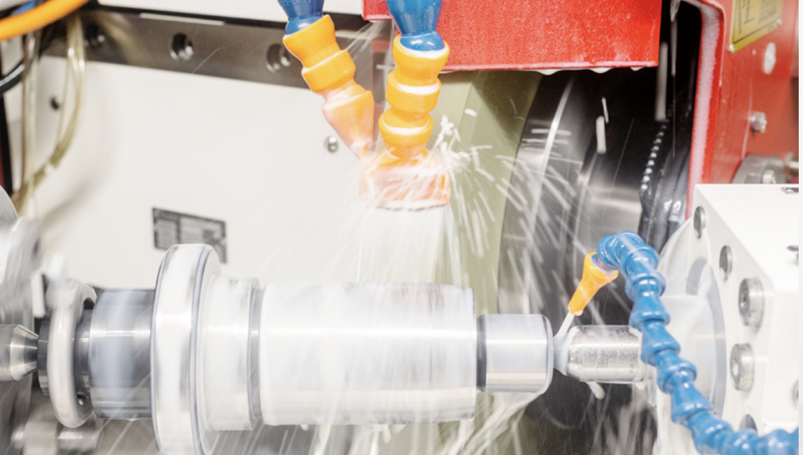
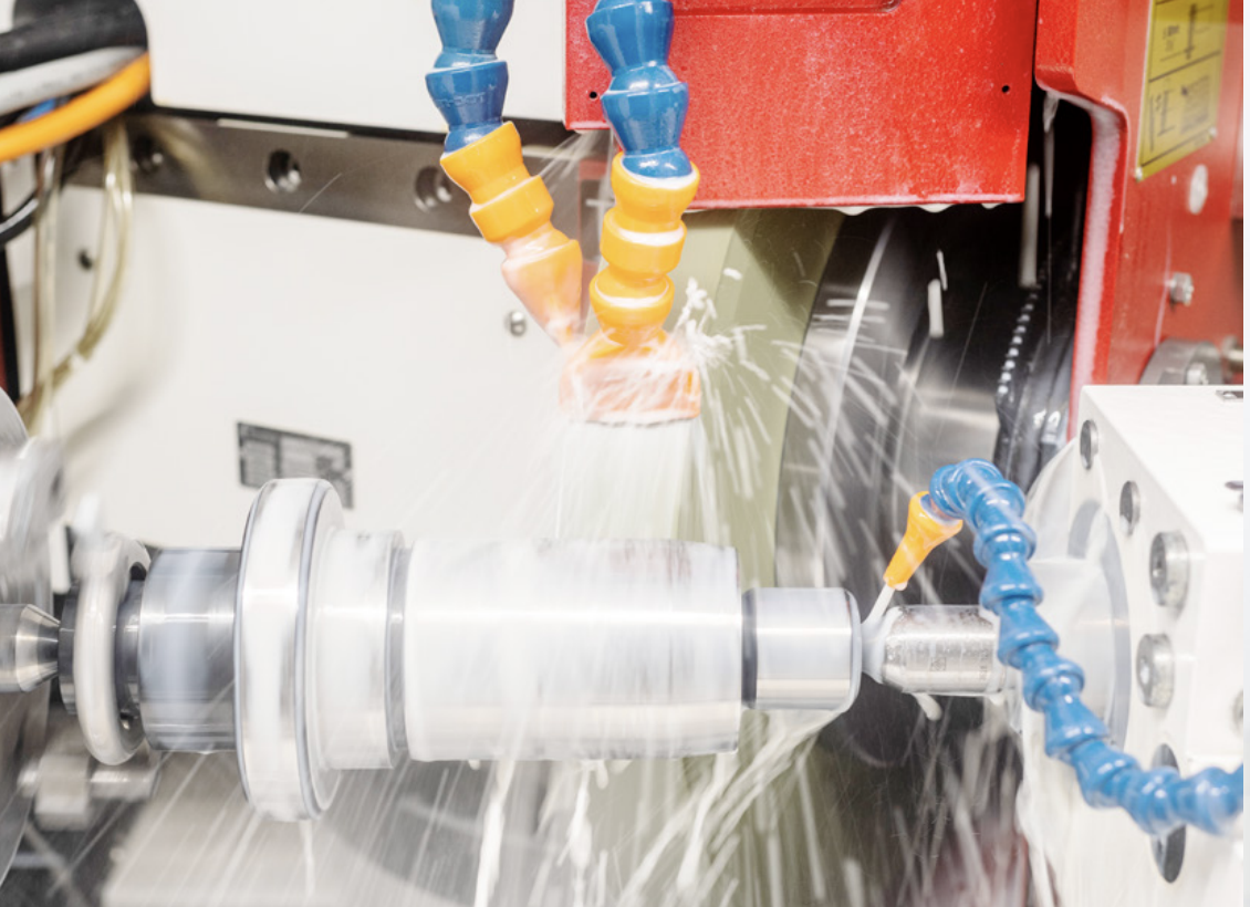
| GENERAL MACHINE INFORMATION |
| Manufacturer |
STUDER |
STUDER |
| Model |
S33 |
S33 |
| Series |
133 |
133 |
| Machine Type |
CNC Universal Cylindrical Grinding Machine |
| Center Distance |
650 mm |
25.59 in |
| Center Height |
175 mm |
6.89 in |
| Center Distance Reduction with Universal Workhead ISO 50 |
50 – max. 200 mm depending on table swivel angle and equipment |
1.97 – max. 7.87 in |
| Machine Base |
Granitan S103 machine base with vibration-reducing mounting pads |
| Guideway Surfacing Material |
Synthetic-based S200 surfacing material with oil circulating lubrication |
| Wheelhead & Longitudinal Slide Guideways |
V and flat guideways |
| Longitudinal Table |
Auxiliary scale for adjusting table mountings |
| Workpiece Table Swivel Range |
+8.5° with fine adjustment and pneumatic lifting for swivelling |
| Mechanical Graduation |
Metric |
| X & Z AXES |
| X-Axis Type |
NC wheelhead axis, driven by AC servo motor via recirculating ball screw |
| X-Axis Travel |
285 mm |
11.22 in |
| X-Axis Programmable Infeed Speed |
0.001 – 10,000 mm/min |
0.00004 – 394 ipm |
| Z-Axis Type |
NC longitudinal axis, driven by AC servo motor via recirculating ball screw |
| Z-Axis Travel |
800 mm |
31.50 in |
| Z-Axis Programmable Infeed Speed |
0.001 – 20,000 mm/min |
0.00004 – 786 ipm |
| X-Axis Measuring System |
Direct linear absolute measuring system – no reference point approach required |
| X-Axis Measuring Resolution |
0.0001 mm |
0.000004 in |
| Z-Axis Measuring System |
Direct linear absolute measuring system – no reference point approach required |
| Z-Axis Measuring Resolution |
0.0001 mm |
0.000004 in |
| Glass Scale Interface |
Equipped for direct measuring systems |
| WHEELHEAD & B-AXIS |
| Wheelhead |
H1 wheelhead |
| B-Axis |
Automatic wheelhead swivel axis with 1° Hirth serration |
| B-Axis Swivel Range |
-15° to +225° |
| Tool Position T3 |
Internal grinding position inclined at -65° |
| Grinding Length Reduction at 30° B-Axis Position – T2/T4 |
75 mm |
2.95 in |
| Grinding Length Reduction for Complete T2/T4 Machining at 0° / 30° |
125 mm |
4.92 in |
| EXTERNAL GRINDING EQUIPMENT |
| External Grinding Wheel Guard – Tool Position T2 |
Ø500 mm wheel capacity |
Ø19.69 in |
| Grinding Wheel Size – T2 |
Ø500 × 63 mm Form 1; up to 80 mm Form 5 |
Ø19.69 × 2.48 in; up to 3.15 in Form 5 |
| External Grinding Wheel Guard – Tool Position T4 |
Ø500 mm |
Ø19.69 in |
| Automatic Grinding Wheel Contact Protection |
Equipped on tool positions T2 and T4 |
| EXTERNAL GRINDING MOTOR SPINDLES |
| Motor Spindle 1 |
Frequency-controlled external grinding motor spindle |
| Motor Spindle 1 Power |
7.5 kW at 1,400 rpm – 11 kW at 3,200 rpm |
10.2 HP at 1,400 rpm – 14.96 HP at 3,200 rpm |
| Motor Spindle 1 Maximum Speed |
3,200 rpm |
| Motor Spindle 1 Cutting Speed |
Programmable up to 50 m/s |
Up to 9,840 sfpm |
| Motor Spindle 1 Shaft |
Solid shaft, one conical shaft end, taper 1:10, nominal Ø63 mm |
Nominal Ø2.480 in |
| Motor Spindle 1 Cooling |
Internal motor-spindle cooling |
| Motor Spindle 2 |
Frequency-controlled external grinding motor spindle |
| Motor Spindle 2 Power |
7.5 kW at 1,400 rpm – 11 kW at 3,200 rpm |
10.2 HP at 1,400 rpm – 14.96 HP at 3,200 rpm |
| Motor Spindle 2 Maximum Speed |
3,200 rpm |
| Motor Spindle 2 Cutting Speed |
Programmable up to 50 m/s |
Up to 9,840 sfpm |
| Motor Spindle 2 Shaft |
Solid shaft, one conical shaft end, taper 1:10, nominal Ø63 mm |
Nominal Ø2.480 in |
| Motor Spindle 2 Cooling |
Internal motor-spindle cooling |
| INTERNAL GRINDING SYSTEM |
| Internal Grinding Attachment |
For high-frequency spindles Ø120 mm |
Ø4.72 in |
| Internal Grinding Position |
Tool position T3, inclined at -65° |
| Lubrication Connection Hose |
Ø4 mm |
Ø0.16 in |
| Coolant Connection Hose |
Ø10 mm |
Ø0.39 in |
| HF Frequency Converter |
15 kW |
Approx. 20.1 HP |
| HF Internal Grinding Equipment |
Designed for Fischer spindles with oil-air lubrication |
| Oil-Air Lubrication Connections |
4 lubrication connections |
| Lubrication Oil Tank |
3 liters |
0.75 US gal |
| Lubrication Monitoring |
Lubrication impulse monitoring, pneumatic pump, oil-level monitoring and pneumatic lubrication-pressure monitoring |
| HF Spindle Sealing Air |
Sealing-air supply when machine energies are ON |
| FISCHER INTERNAL GRINDING SPINDLE |
| Internal Grinding Spindle |
Fischer MFM 1242/60 |
| Internal Grinding Spindle Speed |
42,000 – 60,000 rpm |
| Internal Grinding Spindle Power |
10 kW |
Approx. 13.4 HP |
| Internal Grinding Spindle Diameter |
Ø120 mm |
Ø4.724 in |
| Internal Grinding Tool Holding Fixture |
HJND 28 |
| Internal Grinding Spindle Lubrication |
Oil-air lubrication with 4 lubrication connections |
| Internal Grinding Spindle Cooling |
Water cooled |
| Internal Grinding Quill HJND 28-528 |
Ø5 × 28 mm |
Ø0.196 × 1.102 in |
| Internal Grinding Quill HJND 28-1250 |
Ø12 × 50 mm |
Ø0.472 × 1.968 in |
| Internal Grinding Quill HJND 28-2060 |
Ø20 × 60 mm |
Ø0.787 × 2.362 in |
| Internal Grinding Chuck |
HJNZ 28 with 2 × ER20 collets |
| ER20 Collet Diameters |
Ø3 mm and Ø6 mm |
Ø0.118 in and Ø0.236 in |
| WORKHEAD & C-AXIS |
| Workhead Type |
Universal workhead with roller bearings |
| Workhead Fitting Taper |
ISO 50 |
| External Cylindrical Spindle Nose |
For chucks up to Ø110 mm |
Up to Ø4.330 in |
| Workhead Spindle Bore |
Ø50 mm |
Ø1.968 in |
| Spindle Blocking |
Manual spindle blocking |
| Workhead Cylindricity Correction |
Manual correction with dial indicator and support |
| Roundness Accuracy – Live Spindle Grinding |
0.0004 mm |
0.000016 in |
| C-Axis |
Standard C-axis for cylindrical creep-feed and thread grinding |
| C-Axis Measuring Resolution |
0.0001° |
| C-Axis Drive |
AC servo motor with safety brake |
| Workpiece Drive Power |
4 kW |
5.44 HP |
| Workpiece Spindle Speed |
1 – 1,000 rpm |
| Workpiece Inching Speed |
1 – 50 rpm |
| Workhead Movement |
Pneumatic lifting with hand valve |
| Maximum Load Moment – Universal Workhead ISO 50 |
180 Nm |
132.84 ft-lb |
| Maximum Load Moment – Chuck Workhead ISO 50 |
250 Nm |
184.50 ft-lb |
| Maximum Workpiece Weight Between Centers – 650 mm Center Distance |
80 kg |
176 lb |
| Chuck Control |
Pneumatic control and clamping-force monitoring with adjustable pressure control |
| TAILSTOCK |
| Tailstock Taper |
MT3 |
| Tailstock Stroke |
35 mm |
1.38 in |
| Tailstock Barrel Diameter |
Ø50 mm |
Ø1.97 in |
| Tailstock Barrel Bearing |
Plain bearing |
| Tailstock Travel Control |
Mechanically adjustable |
| Tailstock Fine Adjustment |
±0.04 mm in diameter |
±0.0016 in |
| Tailstock Lifting |
Pneumatic lifting unit for easier positioning during setup |
| Tailstock Park Position |
Equipped with park position within the machine |
| DRESSING SYSTEM |
| Dressing Attachment |
Hydraulic hinged dressing attachment mounted on workpiece table |
| Dressing Capability |
Usable for external and internal grinding without resetting |
| Dressing Tool Holder – Workhead / Tailstock |
Vertically adjustable, 3 shortened MT1 fitting tapers for 2 dressing tools |
| Dressing Tool Holder – Table Dressing Attachment |
Vertically adjustable with 2 oblique shortened MT1 connecting bores |
| Dressing Tool Clamping Length |
19 mm |
0.75 in |
| Thread Grinding Dressing Holder |
Height adjustable; Ø9.52 mm straight bore plus shortened MT1 bore |
Ø0.37 in straight bore plus shortened MT1 bore |
| CVD Dressing Tool |
Type CVD-3-0640 DV/10; height 10 mm; length 18 mm |
Height 0.39 in; length 0.71 in |
| Profile Diamond |
R0.125, 40°, MKD; cylindrical shaft Ø9.52 × 35 mm |
Ø0.37 × 1.38 in shaft |
| CNC CONTROL SYSTEM |
| CNC Control |
FANUC 0i-TD |
| PLC |
Integrated PLC controls |
| Program Memory |
256 kB usable memory / capacity for 400 programs |
| Display |
15-inch flat screen with touch function and integrated PC |
| PC Interface |
USB interface inside and outside operating panel |
| Portable Operating Unit |
STUDER PCU Terminal II with TFT color monitor, keyboard, electronic handwheel, override and acceptance button |
| Working Hour Meter |
0 – 99,999 hours |
| Safety System |
FANUC Dual Check Safety with automatic energy switch-off |
| Ethernet Interface |
Active Ethernet interface for external PC data exchange and remote diagnostics |
| ELECTRICAL DATA |
| Main Voltage |
400 V AC ±10% |
| Main Frequency |
50 Hz ±1 Hz |
| Mains Connection |
4-wire L1/L2/L3/PE or 5-wire L1/L2/L3/N/PE |
| Control Voltage |
24 V DC |
| Electrical Cabinet Air Conditioning |
Equipped |
| CONTACT DETECTION & MEASUREMENT |
| Electronic Contact Detection |
Dittel S6000 |
| Contact Detection Inputs |
2 inputs for active or passive sensors |
| Contact Detection Control |
Display and control through STUDERWIN with programmable sensitivity |
| Contact Detection Input 1 |
5-pole socket on workhead |
| Contact Detection Input 2 |
5-pole socket on workhead |
| Swivelling Touch Probe |
Switching touch probe in tool position T2 with automatic compensation software |
| Touch Probe Measuring Tip |
Ball Ø2 mm × 21 mm length, M3 thread |
Ball Ø0.079 in × 0.827 in length |
| Passive Cut-In Sensor |
Magnetic-base sensor with pluggable connection cable |
| Sensor Cable Length |
6 m |
19.69 ft |
| BALANCING SYSTEM |
| Manual Balancing Interface |
Interface for portable MPM BMT100 / BMT2xx balancing unit |
| Dynamic Balancing Unit |
Portable MPM 3.BMT230-2.M.24 two-plane balancing unit |
| Balancing Unit Supply |
24 V DC |
| Balancing Capability |
Manual adjustment of balancing segments on two grinding wheel flanges |
| Imbalance Sensors |
2 × MPM magnetic-base sensors, Ø25 mm |
2 × Ø1 in sensors |
| Balancing Connection Cable Set |
1.4 m cable length |
4.59 ft |
| SOFTWARE & GRINDING FUNCTIONS |
| Thread Grinding Cycles |
STUDER operating-system thread grinding cycles |
| External Thread Pitch Angle Capability |
Up to 6° |
| Internal Thread Pitch Angle Capability |
Up to 4° |
| Thread Grinding Cycle Types |
Plunge grinding, traverse grinding and traverse grinding with constant removal capacity |
| Program Check with Handwheel |
Equipped – allows control of infeed speed during automatic program cycle |
| STUDER Quick-Set |
Equipped with registering tripod and touching / measuring area |
| Quick-Set Function |
Allows registered grinding wheels to be reused without new setup and supports free swivel grinding angles |
| STUDERThread Integrated |
Integrated thread grinding and contour dressing software |
| Thread Wheel Dressing |
Single and multi-profile wheel dressing with selectable dressing strategies |
| Thread Profile Compensation |
Contour-error and profile-distortion compensation including asymmetric thread profiles with swivelling B-axis |
| DXF Support |
Free-form thread profiles supported through Vector CAD DXF files |
| STUDERWIN Languages |
Czech, German, English, French and Italian |
| Microsoft Operating System Language |
English |
| Control Measurement Units |
Metric |
| HYDRAULIC & PNEUMATIC SYSTEM |
| Hydraulic System |
Two-circuit hydraulic system |
| Main Hydraulic Nominal Pressure |
20 bar |
Approx. 290 psi |
| Lubrication Circuit Nominal Pressure |
0.8 bar |
Approx. 11.6 psi |
| Hydraulic Filter |
10 µm |
| Lubrication Filter |
6 µm |
| Hydraulic Oil Volume |
16 liters |
Approx. 4.23 US gal |
| Pneumatic Basic Unit |
Compressed-air preparation with filter, automatic water separator, electrical main valve and circuit-pressure monitoring |
| COOLANT & FILTRATION SYSTEM |
| Coolant Type |
Mineral emulsion |
| Coolant Interface |
Interface for external coolant supply system |
| Paper Band Filter Capacity |
375 liters |
99 US gal |
| Filter Fleece Width |
1,000 mm |
39.37 in |
| Filter Feeding |
Automatic filter-fleece feeding |
| Coolant Pump – Circuit 1 |
40 l/min at 3 bar |
10.57 US gpm at approx. 43.5 psi |
| Coolant Pump – Circuit 2 |
100 l/min at 2.5 bar |
26.42 US gpm at approx. 36.3 psi |
| Motor-Spindle Water Cooling Circuit |
Passive refrigeration / water-cooling system |
| Cooling-Water Tank |
100 liters |
26.42 US gal |
| Coolant Cycle Valve – T2 |
Process cooling for grinding wheel in tool position 2 |
| Coolant Cycle Valve – T3 |
Process cooling for grinding wheel in tool position 3 |
| Coolant Cycle Valve – T4 |
Process cooling for grinding wheel in tool position 4 |
| Grinding Mist Extraction Connection |
Ø198 mm duct adapter |
Ø7.795 in |
| ENCLOSURE & SAFETY |
| Machine Enclosure |
Full enclosure upgraded from partial enclosure |
| Partial Enclosure Height |
1,575 mm from floor |
62.01 in |
| Coolant Collector |
Integrated coolant collector tray over machine base |
| Machine Lighting |
24 V / 36 W cold-light lamp |
| Door Safety |
Electrical door monitoring and locking mechanism, EC-compliant execution |
| EXTERNAL GRINDING WHEEL ACCESSORIES |
| Wheel Adaptors |
3 × grinding wheel adaptors |
| Wheel Adaptor Diameter |
Ø500 mm |
Ø19.685 in |
| Wheel Adaptor Bore |
Ø203.2 mm |
Ø8 in |
| Grinding Wheel Width |
32 – 63 mm Form 1; up to 80 mm Form 5 |
1.259 – 2.480 in; up to 3.149 in Form 5 |
| Wheel Adaptor Shaft Interface |
1:10 taper, nominal Ø63 mm |
Nominal Ø2.480 in |
| Wheel Adaptor Equipment |
Balancing segments and graduation |
| Spacer Rings |
2 × 15 mm rings, Ø203.2 mm bore |
2 × 0.590 in rings, Ø8 in bore |
| Grinding Wheel Changing Pin |
220 mm length |
8.661 in |
| Static Balancing Arbor |
Ø63 mm nominal, 285 mm length |
Ø2.480 in nominal, 11.220 in length |
| Compatible Static Balancing Equipment |
Ø400 mm or Ø600 mm |
Ø15.748 in or Ø23.622 in |
| INTERNAL GRINDING WHEELS & ACCESSORIES |
| Internal Wheel – Type 1 |
Ø10 × 10 × 4 mm, 54A 80 H 8 V604W |
Ø0.394 × 0.394 × 0.157 in |
| Internal Wheel – Type 1 Cutting Speed |
50 m/s |
9,840 sfpm |
| Internal Wheel – Type 2 |
Ø20 × 20 × 6 mm, 54A 120 H 15 VPMF604W |
Ø0.787 × 0.787 × 0.236 in |
| Internal Wheel – Type 2 Cutting Speed |
50 m/s |
9,840 sfpm |
| Internal Wheel – Type 3 |
Ø32 × 32 × 10 mm, 54A 120 H 15 VPMF604W |
Ø1.260 × 1.260 × 0.394 in |
| Internal Wheel – Type 3 Cutting Speed |
50 m/s |
9,840 sfpm |
| SARUBIN Grinding Wheel |
60M, Ø6 × 8 mm, shaft Ø3 mm |
Ø0.236 × 0.315 in, shaft Ø0.118 in |
| Internal Grinding Wheel Adhesive |
Araldite Rapid two-component adhesive |
| WORKHEAD ACCESSORIES |
| Cut-In Ring Sensor |
Passive transmitter ring for live-spindle grinding with ISO 50 workhead |
| Receiver Ring |
Receiver ring for passive cut-in ring sensor, ISO 50 universal workhead |
| Receiver Ring Cable |
6 m |
19.69 ft |
| Center Adaptor |
MT3 center insert for ISO 50 universal workhead |
| Carrier Set |
For workpiece diameters Ø10 – Ø50 mm |
Ø0.39 – Ø1.97 in |
| Carrier Sizes |
Ø10 / 16 / 25 / 40 / 50 mm |
Ø0.39 / 0.63 / 0.98 / 1.57 / 1.97 in |
| Chuck Adaptor Flange Blank |
Ø185 mm for Ø110 mm spindle nose |
Ø7.28 in for Ø4.33 in spindle nose |
| Maximum Chuck Diameter for Flange Blank |
Ø200 mm |
Ø7.87 in |
| Full Center |
Short Ø26 mm, MT3 |
Ø1.023 in, MT3 |
| Half Center |
Short Ø26 / 4 mm, MT3 |
Ø1.023 / 0.157 in, MT3 |
| CUSTOM GRINDING WHEELS |
| Thread Grinding Wheel |
Ø500 × 40 mm, Form 1, 42A150/180 M10V300W |
Ø19.685 × 1.575 in |
| Grinding Wheel Form 1N |
Ø500 × 25 × 203.2 mm; V=60°; X=3 mm |
Ø19.685 × 0.984 × 8 in; X=0.118 in |
| Form 1N Wheel Specification |
54A120 H15VPMF904W – 50 m/s / 9,840 sfpm |
| Grinding Wheel Form 1 |
Ø500 × 25 × 203.2 mm |
Ø19.685 × 0.984 × 8 in |
| Form 1 Wheel Specification |
54A80 H8V904W – 50 m/s / 9,840 sfpm |
| COOLANT & MAINTENANCE ACCESSORIES |
| Filter Fleece |
Fine OL 50; 150 m roll × 1,000 mm width |
Approx. 492 ft roll × 39.37 in width |
| Coolant Concentrate |
CASTROL Hysol RD |
| Coolant Mixing Ratio |
Approx. 4% |
| Coolant Concentrate Container |
20 liters |
5.28 US gal |
| Cooling Circuit Anticorrosive |
Motorex Coolant F |
| Fungicide |
Motorex Antisept |
| Water Cooling Circuit Cleaner |
Motorex Swisscare SC |
| Radial Dial Gauge |
Metric, graduation 0.002 mm |
Approx. 0.000079 in graduation |
| DOCUMENTATION & MACHINE EQUIPMENT |
| Machine Geometry Certificates |
Included |
| Electrical Test Certificate |
EN 60204-1 including protective-conductor continuity test |
| EC Declaration of Conformity |
Included |
| FANUC Operator Manual |
English |
| FANUC Maintenance Manual |
English |
| Equipment Documentation |
English / German |
| STUDER Control Documentation |
English / German |
| Electrical Schematics |
Included |
| Hydraulic Schematics |
Included |
| Pneumatic Schematics |
Included |
| Coolant Schematics |
Included |
| Software Documentation / Data Backup |
CD-ROM with option programs and parameters |
| Operating Tools |
Included |