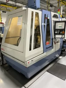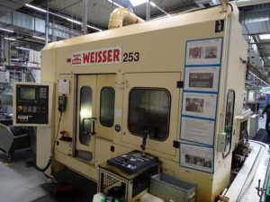
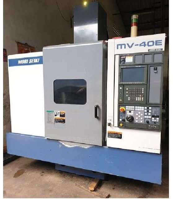
How Smart Engineers Assess a Pre-Owned, Used, Second-Hand, Surplus Mori Seiki MV-40E CNC Vertical Machining Center made in Japan Before Purchase
When a seasoned engineer inspects a used / surplus Mori Seiki MV-40E (or MV-40 family) CNC vertical machining center (Japan) before purchase, they follow a structured, multi-stage approach. The goal: discover latent issues, validate performance, and quantify risk. Below is a “smart engineer’s playbook” — what to check, red flags, and decision criteria.
1. Know the baseline / “spec envelope” first
Before you ever see the machine, you should have a clear understanding of how an MV-40E should perform. That way, discrepancies become red flags rather than surprises.
From listings and spec sheets (various sources):
- Spindle: 8,000 rpm, CAT / BT-40 taper, ~10 HP motor
- Travels: X ≈ 22.0 in, Y ≈ 16.1 in, Z ≈ 18.1 in
- ATC (tool changer): 20 stations
- Control: often Mori’s MSC-500 (Fanuc-style interface)
- Table size / loading: e.g. ~ 35.4″ × 17.7″ table; work load capacity modest
- Other features: full coolant enclosure, spindle chiller, guards etc.
By having this “spec envelope” in your mind, every measured deviation becomes actionable intelligence (i.e. “this axis is weak,” “table load is overstated”).
2. Pre-visit homework & documentation gathering
Before stepping into the workshop, try to collect as much documentation as possible and ask the seller key questions. This helps you weed out bad machines early.
What to request / ask for:
- Full maintenance & repair logs, including dates & replaced parts
- Usage history / total hours & “cutting hours” (how aggressively it was used)
- Original manuals (mechanical, electrical, hydraulics), wiring diagrams, parts lists
- Control / CNC backups, parameter files, original program files
- Any retrofits or modifications (e.g. replaced spindle, changed control, added coolant, probing system)
- Photos, especially internal views (guides, spindle, ATC, wiring)
- Reason for sale & environment it worked in (e.g. clean shop, heavy production, dusty, corrosive)
- Whether the seller allows functional test / return clause
If the seller is reluctant to provide credible documentation or to permit a trial, that’s a red flag worth discounting heavily.
3. Visual & structural inspection (walk-around)
Once on site, carry out a methodical visual inspection. Many fatal flaws can be seen with eyes, feel, and light.
Frame, Base & Enclosure
- Examine the machine base / bed / casting for cracks, weld repairs, distortions, signs of shifting or re-shimming.
- Check whether the machine appears plumb / level or if there are signs of repeated leveling adjustments.
- Inspect the enclosure, guards, doors, panels — broken or missing panels are not just cosmetic issues; they often hint at abuse or neglect.
- Look for rust, corrosion (especially in the coolant / sump / underside sections) or evidence of water ingress.
Guideways, Slides & Way Covers
- Carefully inspect the X, Y, Z guideways / rails for scoring, pitting, galling, or uneven wear.
- Remove or lift protective way covers (if safe) to examine underlying metal surfaces.
- Check gibs, wipers, scrapers, seals; missing or damaged wipers allow chips & coolant ingress, accelerating wear.
- Look for “cure marks” — grooves or wear more severe on one side, which could indicate misalignment or uneven loading.
Spindle Housing & Front End
- Examine the spindle nose taper, face, and mounting surfaces for damage, corrosion, nicks.
- Look for oil or grease stains (possible seal leaks) or coolant intrusion in spindle area.
- Inspect the front end cover, bearings housing, and housing seals.
- In some machines, access observation ports or inspect internal covers if possible.
ATC / Tool Changer & Tool Magazine
- Inspect the magazine, arms, grippers, drive mechanisms, indexing mechanism.
- Look for wear, play, damage, misalignment.
- Check if the magazine rotates smoothly, without binding, and whether tool release / grip mechanisms seem robust.
- Inspect tool holder pockets, hard stops, and interface surfaces for wear or distortion.
Electrical / Control Cabinet & Wiring
- Open control / drive cabinets. Look for signs of overheating: scorched wires, melted insulation, discoloration.
- Inspect cable routing, strain reliefs, cable supports, and whether wiring is neatly labeled or ad hoc.
- Check for aftermarket modifications, splices, or mismatched wiring which may indicate prior failures or patches.
- Inspect connectors, power supplies, I/O cards, backplanes for corrosion or damage.
4. Motion / mechanical / axes & dynamics checks
After visual checks, the next step is to test movement, measure play, and see how axes behave (ideally with power, but even manually where possible).
Axis Motion & Behavior
- Jog each axis (X, Y, Z) slowly and at faster traverse rates. Listen and feel for smoothness, binding, stuttering, or hesitation.
- Reverse direction frequently and check for dead zones, backlash, or hysteresis.
- Stop mid-move and see if axes “creep” (drift) under load — such “drift” suggests worn nuts, loose backlash, or hydraulic / servo leakage.
- Repeat position commands multiple times to assess repeatability (e.g. go to the same point 5 times and measure spread).
Spindle Run-up & Test
- Ramp the spindle from low rpm up to full rpm (if allowed). Listen & feel for bearing noise, vibration, or unusual hum.
- Measure runout with a test bar or dial indicator (spindle nose, internal taper) to assess radial / axial play.
- Observe vibration or resonance zones (does it vibrate at certain rpm bands?).
- Test tool clamping / release (pull tool in and out, see if it holds firmly, check for slippage).
Load / Cut Test
If the seller allows, request a light cutting test with a typical workpiece (or test bar). This is where many defects manifest.
- Run a simple milling pass, probing cut from multiple positions in work envelope.
- Inspect resulting part: measure dimensional accuracy, surface finish, variation across different parts of the work envelope.
- Run repeated passes to see drift over cycles.
- Observe machine noises, coolant behavior (splash, leaks), thermal drift effects.
- During the cut test, trigger rapid moves, direction changes to stress drive systems.
Tool Change / Magazine Test
- Command a full series of tool changes, sequentially, back and forth.
- Check for hesitation, mis-indexing, tool drop, slips.
- Use heavy tools and light tools to check if the mechanism is robust for the extremes.
- Observe whether the magazine rotation and tool handling remains precise under use.
5. Precision, measurement & calibration verification
Bring precise measurement instruments (gages, dial indicators, surface plate, test bars) and carry out these checks:
- Backlash / hysteresis in X, Y, Z (measure movement when direction reversed).
- Repeatability: command same position multiple times and measure spread.
- Straightness / flatness: measure linear paths, e.g. X over Y, or Z over a known reference.
- Spindle runout (external and internal) using test bar or sensitive dial indicator.
- Surface finish / part validation: check a test part’s dimensional tolerances and surface finish across the work envelope.
- Flatness / squareness / perpendicularity: check whether axes are properly orthogonal (X ⟂ Y, Y ⟂ Z, etc.).
- Thermal drift / stability: after running for some time, let the machine cool and re-measure key points to see drift.
If deviations are within acceptable tolerances for your production use, that’s good; if they exceed what your parts require, you must evaluate cost to recondition (ways, ball screws, spindle bearings, realignment).
6. Wear, fatigue & hidden damage assessment
Many issues in used CNC machines are hidden, not obvious — and those are the ones that cost you later.
- Lubrication system health: inspect lube lines, pumps, distribution lines, reservoirs. Dry or blocked lubrication suggests neglect.
- Way cover / wiper damage: missing or torn covers expose guideways to chips / coolant, accelerating wear.
- Hydraulic / pneumatic systems (if present): leaks in cylinders, servo valves, pistons or fluid contamination.
- Cable / harness fatigue: moving cables (to axis motors, spindle, tool magazine) often fail internally — look for cracked jackets, worn insulation, pinching points.
- Control / electronics aging: capacitors, fans, power supplies degrade over time. Look for bulging caps, dust buildup, failed cooling fans.
- Past collisions or crashes: ask the seller: has the machine ever crashed an axis, over-traveled, or had sudden stops? Such events can bend frames or misalign axes.
- Parts obsolescence: control electronics, spindle parts, replacements may be out of production; verify spare parts availability.
7. Support, parts & future maintainability
A good used machine is only as good as your ability to support it going forward.
- Confirm availability of spare parts: spindle bearings, drive motors, control boards, tool changer parts, sensors.
- Check whether Mori Seiki (or successor company DMG Mori) or third-party suppliers still support this model / control.
- Ask whether the seller includes spare modules, cables, spare parts, tooling, or accessory kits.
- Assess whether local service shops or CNC repair houses are capable of supporting this machine.
- If the control / electronics are non-standard or heavily customized, assess whether replacements or retrofit options exist.
8. Pricing negotiation & risk buffer
Once you have an itemized “defect / discrepancy list,” you can negotiate rationally.
- Obtain repair / recond costs (spindle rebuild, alignment, ways refurb, electronics repair).
- Subtract expected costs from asking price — your “net value.”
- Include costs of transport, rigging, leveling, reassembly, calibration, commissioning.
- Leave a contingency margin (say 10-20 % or more) for hidden issues you didn’t catch.
- Where possible, negotiate a short acceptance / test period so you can uncover post-installation issues.
- Consider requiring the seller to guarantee certain tolerances or performance during initial operation.
9. Installation & commissioning best practices
Once you purchase and bring it to your shop, follow a disciplined commissioning process.
- Foundation & leveling
- Ensure a stable, rigid base or concrete pad.
- Precisely level the machine (laser or electronic methods).
- Allow room for thermal expansion and anchoring. - Utilities & environment
- Stable power supply (three-phase, voltage stability, grounding).
- Clean environment (low dust, temperature control).
- Proper coolant / chip management systems. - Flushing / cleaning & fresh fluids
- Drain and flush cooling systems, lubrication systems, hydraulic fluids (if applicable).
- Replace filters, seals, clean reservoirs.
- Replenish with clean, manufacturer-specified fluids. - Re-alignment & calibration
- Recheck and adjust axis alignment, orthogonality, backlash compensation, encoder zeroing.
- Run calibration routines / self-tests (if control supports).
- Measure reference benchmarks and compare to factory specs. - Break-in & stabilization runs
- Start with light, conservative cuts and operations.
- Monitor for drift, thermal growth, loosening of nuts, shifting of alignments.
- Over the first 100–500 hours, re-measure critical alignment points to detect creeping drift. - Baseline measurements & logging
- Capture baseline metrics (runout, backlash, repeatability) after break-in.
- Maintain detailed logs of adjustments, wear trends, calibration shifts. - Operator training & preventive maintenance
- Train operators on safe practices, collision avoidance, understanding machine limits.
- Set up a maintenance schedule (daily, weekly, monthly) to check lubrication, axis performance, coolant, filters.
10. Red-flag “deal-breaker” criteria
If you encounter one or more of the following, you should be very cautious (or walk away):
- Spindle with excessive radial / axial play, noise, or degraded bearing behavior
- Guideways / rails severely scored, damaged, or worn beyond repair
- Missing or badly damaged way covers / wipers
- Control electronics badly damaged, missing, or proprietary to the point of unmaintainable
- Tool changer / ATC mechanism faulty, mis-indexing, or excessively worn
- Axis motion with significant drift, binding, or hysteresis
- Past collisions or axis crashes not properly repaired
- No or poor support / spares for critical components
- Seller refuses any functional test or measurement verification
- Repair, refurbishment, transport, and calibration costs approach or exceed the “discount” from buying new