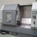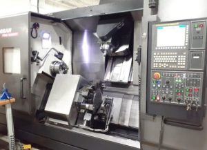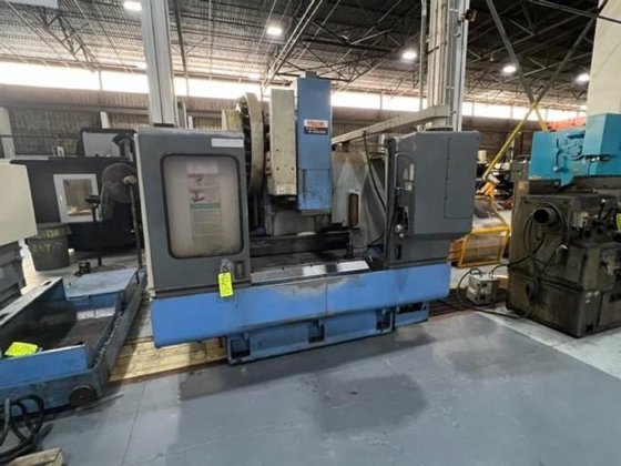
From Factory Floor to Your Workshop: Evaluating a Pre-Owned , Used , Secondhand, Surplus CNC Machines Before Purchase Mazak V414 CNC Vertical Machining Center made in Japan
Here is a comprehensive “Factory Floor → Workshop” style evaluation guide for a Mazak V414 (vertical machining center, made in Japan). Use this when you’re assessing a used / surplus unit. I also include reference specs from used-machine listings so you have benchmarks.
Reference Specs & Baseline Data (Mazak V414)
Before you inspect, it’s helpful to know what specs are typical for a Mazak V414 so you can detect exaggerations or deviations. Here are some published / listing data:
| Parameter | Typical / Published Value | Source / Notes |
|---|---|---|
| X travel | ~ 22.05″ (≈ 560 mm) | Mazak V-414 listing: X = 22.05″ |
| Y travel | ~ 16.14″ (≈ 410 mm) | Same listing: Y = 16.14″ |
| Z travel | ~ 18.11″ (≈ 460 mm) | Same listing: Z = 18.11″ |
| Table size | 35.43″ × 16.14″ | Multiple listings show table size = 35.43″ × 16.14″ |
| Spindle speed | Up to ~ 7,000 rpm | Many listings: 50 – 7,000 RPM |
| Spindle power / horsepower | 10 HP / ~7.5 kW | A listing lists “Spindle Motor, 10 HP” |
| Tool magazine / ATC | 24 station (some units) / 30 station in others | Some listings show 24 tool count others show 30 tools for variants |
| Rapid traverse (X/Y) | ~ 945 IPM | One listing: rapid traverse X/Y = 945 IPM |
| Rapid traverse (Z) | ~ 590 IPM | Same listing: Z rapid = 590 IPM |
| Spindle taper | CAT-40 / #40 | Listings indicate spindle taper = 40 (Mazak “V-414” uses #40 / CAT40) |
| Table-to-spindle nose clearance | 5.91″ min – 24.02″ max | From listings: “Distance Spindle Nose to Table Top: 5.91 – 24.02″ |
These specs give you a “target envelope.” If you see claims well outside those ranges (e.g. 15,000 rpm, 40″ X travel) without evidence, you should insist on verifying.
Evaluation / Inspection Checklist
Below is a phased inspection plan you can bring with you. Use proper measurement tools (dial indicators, test bars, calipers) and ideally have a machinist or technician accompany you.
Phase 1: Pre-Screening & Documentation Review (Before Visiting)
Ask the seller to provide:
- Clear photos of nameplates (mechanical & electrical) showing model, serial, build year
- The machine’s original spec sheet / brochure / manuals
- Control system type, software version, parameter file backups
- Run hours: more importantly, cutting (load) hours vs idle hours
- Maintenance / repair history (spindle rebuilds, ball screw replacements, guideway repairs)
- List of included tooling, fixtures, spare electronics
- Photos / video of machine in operation (axis motion, spindle running, tool changes)
- Reason for sale (upgrade, closure, fault)
- Shop environment: how “clean” was it, coolant type, chip management, corrosive exposure
- Logistics / rigging info: machine dimensions, weight, foundation, crane access
If many of these are missing or the seller is evasive, that’s a red flag.
Phase 2: Visual & Structural Walkaround
On arrival:
- Inspect the casting / base / column for cracks, weld repairs, distortions
- Examine way surfaces / slides / guideways for pitting, scoring, uneven wear
- Check way covers, bellows, guards for tears, missing parts or misalignment
- Inspect the spindle housing, chuck, nose taper, turret / tool changer area for damage or wear
- Inspect wiring, cable carriers, junction boxes for splices, exposed insulation, fatigue
- Look for coolant / oil leaks around seals, sliding surfaces, pumps
- Check the ATC / tool magazine / arm (if present) for mechanical wear, alignment, smoothness
Gently jog axes (in safe / manual mode) if possible to detect binding or uneven motion.
Phase 3: Axes Motion, Backlash & Kinematics
- Jog X, Y, Z axes slowly across full travel; feel for stick-slip, binding, inconsistent motion
- Use dial indicators to measure backlash / lost motion in each axis (push-pull) at several positions
- Reverse direction near ends to detect hysteresis / deadband
- Inspect ball screws, nuts, couplings, bearings for looseness or play
- Command slow feed moves; look for jumps, hesitation, stutters
- Cycle the tool changer multiple times and watch for mis-index, delay, or skew
Phase 4: Spindle, Tooling & Tool Change Mechanism
- Run the spindle at multiple speeds; listen / feel for bearing noise, wobble, vibration
- Use a test bar + dial indicator to measure spindle runout at the nose (and if possible further out)
- Check spindle acceleration / deceleration response
- Examine the taper, clamping surfaces, chuck mounting seat for wear / damage
- Operate the ATC / tool magazine: watch tool pick / placement, clamping force, indexing accuracy
- If equipped with fourth axis or rotary table, test indexing / rotation under no load, measure backlash
Phase 5: Control / Electrical / Cabinet Inspection
- Open electrical cabinets and inspect wiring, terminal blocks, fuses, relays, PCBs
- Look for overheating signs: discolored insulation, burnt connectors, melted parts
- Check servo drives, interface modules, amplifiers for damage or corrosion
- Check cable routing, shielding, strain reliefs
- Power up the control panel: test switches, override knobs, emergency stop, limit switches / interlocks
- Navigate CNC menus: check parameter sets, tool tables, alarm logs, memory backups
- Test safety interlocks: opening guards should disable motion
- If linear scales / encoders installed, verify they respond correctly
Phase 6: Operational / Test Cut & Live Load Testing
If seller permits:
- Run a dry / air motion program exercising all axes (X, Y, Z) and tool change sequences
- Perform a test cut (mild steel / aluminum) to evaluate surface finish, chatter, dimensional control
- Run a sustained cut (30–60 min), then remeasure axes / tool offsets to detect thermal drift
- After warm-up, repeat backlash / motion tests to see if they’ve changed
- Cycle tool changes many times to assess consistency
- If 4th axis / rotary table is present, test under load if possible
Phase 7: Accuracy, Precision & Metrology Checks
- Use gauge blocks, test bars, or master artifacts to check geometry (straightness, squareness, alignment)
- Test repeatability: move to a point, retract, return, measure deviation
- Inspect test-parts for dimensional accuracy, circularity, runout
- After extended cycles, re-check offsets, tool height, backlash for drift
- Compare measured performance to your part tolerances and to those spec ranges listed above
Phase 8: Infrastructure / Installation / Practical Concerns
- Confirm your shop floor load capacity is adequate
- Verify crane / rigging / shop layout / clearance are sufficient for removal and installation
- Ensure your power supply (voltage, phase, current capacity) is compatible
- Check coolant / filtration / chip removal systems, chip conveyor, flood flood coolant
- Plan for leveling, anchoring, foundation repair / adjustment
- Ensure access for service: control cabinet, motors, slides, spindle area
- Confirm availability of spare parts for Mazak V414 / Mazatrol controls in your region
Phase 9: Decision / Negotiation Criteria & Red Flags
After all testing and measurement, consider:
Positive / Acceptable Signs:
- Measured travels, spindle rpm, table size close to spec
- Smooth motion, low backlash, consistent performance
- Spindle runs quietly, low vibration, acceptable runout
- Tool change / magazine works reliably
- Control / electronics are intact, no burnt modules, parameters accessible
- Test cuts produce good finish, minimal drift
- Performance stable after warm-up (minimal thermal change)
- Spare parts or control support for Mazak is available
Red Flags / Deal Breakers:
- Major deviation from claimed spec (travel, rpm, spindle power) without proof
- Severe wear on ways, binding motion, inconsistent backlash
- Noisy spindle, excessive runout, vibration
- Tool change failures, mis-index, tool jamming
- Burnt wiring, failed modules, corrupted control memory
- Test cuts show drift, chatter, tolerance deviations
- Behavior shifts after warm-up (thermal instability)
- Critical parts obsolete or unserviceable
- Seller refuses live test, documentation, or warranty agreement
Use any defects you uncover as negotiation leverage — demand inclusion of spare modules, discount, or a short-term performance guarantee.