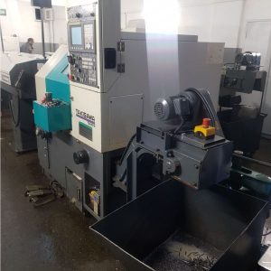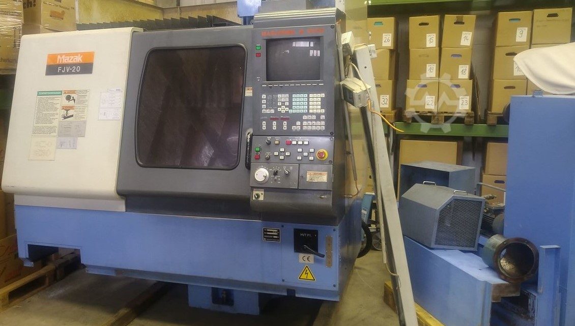
From Factory Floor to Your Workshop: Evaluating a Pre-Owned , Used , Secondhand, Surplus CNC Machines Before Purchase Mazak FJV-20 CNC Vertical Machining Center made in Japan
Here is a tailored “Factory Floor to Your Workshop” evaluation guide for a Mazak FJV-20 CNC vertical machining center (Japan origin)—covering what to expect, how to inspect, which tests to run, and decision criteria. I’ll also include published specs / red-flag thresholds for reference.
Known / Reference Specifications & Model Context for Mazak FJV-20
Before inspection, having expected values helps you spot exaggeration or hidden problems. Below are data compiled from used listings and dealer listings:
| Spec | Typical / Published | Notes / Sources |
|---|---|---|
| X / Y / Z travel | ~ 22.05″ / 16.14″ / 16.14″ | From The Equipment Hub listing for FJV-20 |
| Table size | ~ 31.49″ × 18.11″ | From the same listing |
| Spindle speed | ~ 12,000 rpm | As listed in the Revelation Machinery ad |
| Spindle motor / power | ~ 25 HP | Revelation listing shows 25 HP |
| Tool magazine / capacity | ~ 20-21 tools | Revelation ad shows ATC 21 tools |
| Taper / tool shank | CAT 40 | Revelation ad states CAT-40 |
| Machine weight / footprint | ~ 9,000 lb (~4,100 kg) | Revelation ad gives ~9,000 lb |
| Control | Mazatrol M-Plus; also Mazatrol / CNC interface | Revelation ad uses Mazatrol M-Plus |
| Bridge / structural style | Bridge type / high-speed VMC | Dealer listing refers to “bridge” vertical machine |
These specs set your “expected envelope.” If seller claims much higher travels, spindle speeds, or heavier duty, ask for proof (cutting tests, internal logs) or treat them critically.
One anecdote from a user:
“We are buying use Mazak FJV-20, year 1997. Machine has new spindle bearings (steel). Axis play is less than 4 µm.”
But also warns: tool changer “umbrella style” fingers are fragile; broken tool changer parts are expensive.
So prior users point out tool changer reliability and precision / backlash stability as common stress points.
Inspection & Evaluation Checklist
Below is a phased plan you can carry when visiting the machine.
Phase 1: Pre-Visit / Documentation Request
Before traveling:
- Ask for nameplate photos (mechanical, electrical) to confirm model, serial, year.
- Request specification sheet or original Mazak documentation.
- Ask for control / CNC version, parameter backups, control logs.
- Ask for usage / runtime history: power-on vs cutting hours, workload profile.
- Maintenance / repair records: spindle rebuilds, guideway refurbishing, ATC repairs.
- Included tooling, fixtures, spare parts (e.g. tool changer fingers, collets).
- Photos / video of machine in operation (spindle, axis moves, ATC).
- Reason for sale (upgrade, failure, relocation).
- Shop environment (coolant type, chip management, dust).
- Layout / rigging / footprint / crane access information.
If the seller is evasive or missing many of these, treat that as a caution sign.
Phase 2: Visual & Structural Inspection (On Site)
Bring measurement tools (dial indicators, test bars, squares), and proceed systematically:
- Examine the machine frame / base / column / bridge for cracks, repairs, distortions, or warpage.
- Check guideways / linear rails / ways (X, Y, Z) for pitting, scoring, corrosion, uneven wear.
- Inspect way covers, bellows, guards for tears, missing pieces, or misalignment.
- Inspect the spindle housing / nose / taper seating surfaces for damage, wear, or misalignment.
- Inspect the tool changer / ATC system (arms, umbrella fingers, magazine) for visible wear, broken fingers, misalignment.
- Inspect wiring, cable carriers, junction boxes for patched wires, exposed insulation, loose conduits.
- Look for coolant / oil leakage along ways, seals, pump areas.
- If there’s a work table, verify mounting surface for flatness, damage, warpage.
Where safe, jog axes in manual / slow mode to feel for binding spots or irregular motion.
Phase 3: Motion, Backlash & Kinematics Tests
- Jog X, Y, Z axes slowly across full travel; feel for smoothness or zones that exhibit “notchiness” or binding.
- Use dial indicators to measure backlash / lost motion in each axis (push-pull) at multiple positions.
- Reverse direction near extremes to detect hysteresis / deadband.
- Inspect ball screws, nuts, couplings, bearings for play, slack, side play.
- Command small feed moves; watch for any jitter, stutters, or non-linearity.
- Cycle tool changes / magazine moves multiple times to check for mis-indexing, hesitation, or deviation.
Phase 4: Spindle, Tooling, ATC Testing
- Run the spindle (if safe) at different RPMs and listen / feel for bearing noise, vibration, runout.
- Use a test bar + dial indicator to measure spindle runout at the nose and ideally along length.
- Check spindle acceleration / deceleration response.
- Inspect taper and seating area for wear, nicks, damage.
- Operate the tool changer / ATC: observe tool pick / placement, indexing, clamping force.
- If the machine has probe or tool length compensation hardware, test these features.
Phase 5: Control / Electrical / Cabinet Inspection
- Open the electrical / control cabinets; examine wiring, fuses, relays, terminal blocks, drives.
- Look for signs of overheating: discolored insulation, melted wires, burnt components.
- Inspect drives, interface cards, control boards for damage, corrosion, or burned traces.
- Check wiring routing, shielding, strain reliefs, connector integrity.
- Power up control panel: test buttons, switches, emergency stop, limit switches / interlocks.
- Operate through the CNC interface: review parameter settings, tool tables, alarm logs, memory backups.
- Check safety interlocks (guard doors, etc.) to ensure they properly disable motion.
- If encoders / feedback scales exist, verify their readings respond correctly.
Phase 6: Operational / Test Cut & Load Run
If seller permits:
- Run a dry / air movement program that exercises axes, tool change, probe, etc.
- Perform a test cut (mild material) to check surface finish, dimensional accuracy, chatter behavior.
- Run a sustained machining cycle (30–60 min); after, remeasure critical axes, backlash, and tool offsets to detect drift.
- After warm-up, repeat earlier tests (backlash, runout) to see if behavior changed.
- Cycle ATC many times to test repeatability, wear, mis-indexing, failure over repeated cycles.
Phase 7: Metrology / Accuracy Checks & Drift
- Use gauge blocks, test bars, squares to check alignment, straightness, squareness.
- Test repeatability / reversal error: move to a reference point, retract, return, measure deviation.
- Inspect test-parts for dimensional accuracy, circularity, tolerance deviations.
- After extended running, re-check offsets, backlash, runout to detect drift.
- Compare results vs your part tolerance requirements and vs expected spec tolerances.
Phase 8: Shop / Infrastructure / Installation Readiness
- Ensure your shop floor can support the machine weight and dynamic loads.
- Check crane / rigging path, door clearances, overhead obstructions.
- Validate your power supply (voltage, phase, current) compatibility.
- Ensure coolant / filtration / chip removal systems are adequate.
- Prepare for leveling, foundation shimming, grouting, anchor points.
- Ensure space for access to all sides, maintenance clearance, electrical cabinet access.
- Confirm spare parts / support availability for Mazak FJV / Mazatrol parts in your region.
Decision Criteria & Red Flags
After inspections, your findings should steer your decision. Here’s a rubric:
Good / acceptable signs:
- Measured axis travels, spindle rpm, table size are close to spec
- Smooth motion, low backlash, consistent axis response
- Spindle runs quiet, low vibration, acceptable runout
- Tool changer / ATC is reliable, no jamming or mis-index
- Control system and electronics are intact, no burnt components
- Test cuts show good surface finish, dimensional stability
- Tolerances hold after warm-up (minimal drift)
- Essential spares / documentation included or available
Red flags / potential deal-breakers:
- Significant deviation from claimed spec (e.g. spindle speed, travel lengths)
- Heavy wear, binding zones, inconsistent movement, large backlash
- Noisy or vibrating spindle, excessive runout
- Tool changer failures, broken fingers, mis-indexing
- Burnt or missing control modules, wiring damage, software corruption
- Test cuts show chatter, drift, offsets beyond tolerance
- Behavior changes after warm-up (thermal drift)
- Lack of spare parts or support for Mazak FJV line
- Seller refuses test cut, denies documentation or warranty
Use any discovered defects as negotiation points—ask for spare parts, discount, guarantee, or repair work inclusion. Document every test, measurement, photo and video.