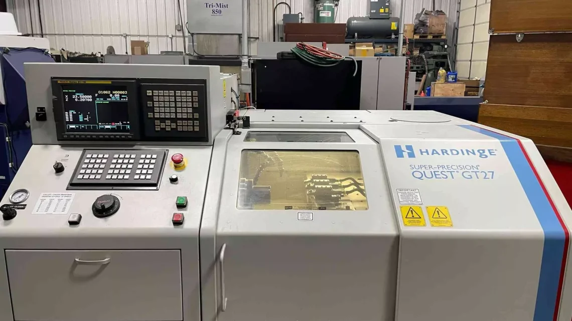
From Factory Floor to Your Workshop: Evaluating a Pre-Owned , Used , Secondhand, Surplus CNC Machines Before Purchase Hardinge Quest GT27 CNC Gang Tool Lathe made in USA
Here’s a tailored and deep-dive guide for evaluating a pre-owned / surplus / secondhand Hardinge Quest (or Conquest) GT27 CNC gang-tool lathe before purchase. Many of the checks parallel those for other CNC lathes, but I’ll call out what’s special about the GT27 family, what to expect, and what to dig into.
If you like, I can turn this into a laminated checklist you can carry into shops.
0. Know the baseline: GT27 specs & special features
Before inspection, familiarize yourself with what a “healthy” GT27 should be able to do. That gives you a benchmark for what’s acceptable vs a red flag.
Here are some representative published specs and features:
| Spec / Feature | Typical Value / Range | Notes & Why It Matters |
|---|---|---|
| Swing over bed / ways | ~ 11.76″ (≈ 298.7 mm) | This tells you the maximum diameter part you can turn. |
| X-axis travel | ~ 11.968″ (304.2 mm) | Used to evaluate whether the machine has full travel or whether modifications have reduced it. |
| Z-axis travel | ~ 11.062″ (281 mm) | For longer parts you’ll want verify full Z travel. |
| Spindle speed range | 80 to 8,000 RPM typical (1-RPM steps) | Watch for drives, control limitations, or modifications. |
| Spindle motor / power | ~ 10 hp (7.5 kW) nominal for standard units | If the motor is undersized or severely degraded, performance will suffer. |
| Collet-ready spindle / hybrid workholding | Yes — can accept both collets and jaw chucks without adapter | This is one of the GT’s selling points; ensure the mechanism still functions well. |
| Control / CNC type | FANUC 32-bit or FANUC 21i (or other variants depending on vintage) | Control health, memory, and compatibility are critical. |
| Weight / footprint | ~4,500–5,700 lb or more, footprint ~ 77″ × 58–60″ × ~ 64″ high | To plan transport, shop layout, foundation, etc. |
| Coolant, air, power, options | 230 V, 3-phase power; coolant tank ~ 20 gal; air supply 70–90 psi ∼5–6 scfm; possible high pressure coolant, chip conveyor, autoloader, etc. | Confirm all auxiliary systems are present and in working order. |
Because GT27 units may come from various vintage years or with retrofit upgrades, the “actual” spec might differ. So, part of your job is to confirm whether the machine still meets (or is close to) these baselines.
One more note: Hardinge published a maintenance manual covering Conquest / GT27 / GT27SP models, which you should try to get ahead of time — it contains service intervals, lubrication details, and internal system layouts.
1. Pre-visit preparations & document requests
Before you walk into the factory or shop, collect as much information as possible. This gives you leverage and lets you tailor your inspection.
Ask in advance:
- Machine serial number, build year, model variant (GT27, GT27SP, Conquest, etc.).
- Maintenance / service history: date of last overhaul, bearing replacements, repairs.
- Usage history: what materials were machined (aluminum, steel, exotic alloys), duty cycles, number of shifts.
- Runtime or hours (if the control tracks it).
- List of installed options: autoloaders, high pressure coolant, chip conveyor, barfeed interface, parts catcher, tool touch probes, etc.
- Control version, firmware version, backup files, spare control boards.
- Electrical and utility requirements (power, air, coolant, shop layout).
- Existing tool setup (types of collets, top plates, tooling).
- Photos / videos of the machine running (if possible).
- Any known faults, repairs, or issues.
Bring with you:
- Precision measurement tools: dial indicators, gauge blocks, test bars, edgefinders, micrometers, etc.
- A test NC part / simple program to run during inspection.
- A structured checklist (mechanical, control, electrical).
- Technician or machinist help (if possible) for deeper diagnostics.
2. Visual / external inspection
This is your first impression — many critical warning signs show early.
- Check the frame, base, bedways, castings for cracks, weld repairs, distortions, or deviations.
- Inspect the machine’s surface: rust, pitting, excessive paint wear, mismatched repairs.
- Are all panels, covers, guards, doors present, intact, and properly aligned?
- Look inside enclosures for chip build-up, corrosion, coolant residue.
- Check the fasteners, bolts, guards — missing, loose or mismatched bolts are red flags.
- Inspect fluid lines (hydraulic, coolant, lubrication) — hoses, clamps, leaks, aging.
- Check leveling screws / foot pads — are they uniform, matching, and not severely adjusted (which might suggest past shifts or settling)?
- Examine the spindle nose area (taper, face, seal covers) for damage or signs of tool interference.
- Inspect the carriage / cross slide top plates and tool mounts for wear or damage.
- Check cable management: wiring harnesses, cable drag chains, conduit routing.
- Examine the condition of the control panel: buttons, screen, overlays, signs of repairs or replacements.
- Inspect the coolant tank (if visible): is it clean, rusted, partially filled, sludge or chip accumulation?
If the exterior is heavily abused or neglected, it’s likely internal wear is also significant.
3. Mechanical & motion systems
Now dig into the machine’s fundamental motion systems — these determine precision and longevity.
Spindle & bearings
- Power up the spindle (at slow speeds first) and listen / feel. Any grinding, squealing, or vibration is a serious warning.
- Try a “run-in / run-out” test: mount a test bar or arbor and measure run-out at the nose and farther away.
- With spindle running, feel for heat in the housing (carefully) — excessive heat may indicate failing bearings or lubrication problems.
- Tap lightly on the spindle nose or mount (with non-damaging tool) and observe if there is play or movement.
- Check if the collet-to-spindle interface is tight, clean, and free of damage (especially important for GT27’s collet-ready design).
- Inspect internal bearing seals (if accessible) for leaks or contamination.
Guideways / slides / axes
- In “jog” manual mode, move X and Z axes slowly through their full range. Watch for stiff spots, jerky motion, or “dead zones.”
- Use a dial indicator or test bar to check straightness and linear alignment of slides.
- Measure backlash in each axis (X, Z) from both directions.
- Check lead screws / ball screws: inspect for wear, scoring, looseness, backlash, or binding.
- Inspect anti-backlash nuts, couplings, and associated hardware.
- Inspect lubrication — are grease/oil ports present, open, clean? Is there evidence of starvation in certain areas?
Gang-plate / tool mounting / top plate system
- Verify that the top plate / gang plate interchanges properly (if this is a feature) and that registration pins or guides still align.
- Inspect tool holders, tool post seats, and mounting surfaces — any excessive wear, play, or looseness is concerning.
- If live tooling or driven tooling is present, test rotation, torque, run-out, and the integrity of the drives.
- Index or shift tools (if the design allows) and observe for slop or misalignment.
- Check hydraulic or pneumatic actuation (if any) for leaks, smoothness, and pressure.
Tailstock / steady rests (if applicable)
- If a tailstock or steady rest is present, check alignment, quill movement, locking, and whether it “rocks” or has play.
- Test that the tailstock, when used, aligns properly along the Z axis.
Chip handling / coolant / auxiliary systems
- Run the chip conveyor (if present) — see if it runs smoothly, jams, or vibrates.
- Test coolant pump(s): is the flow strong? Are there leaks, cavitation, or noise?
- Inspect coolant nozzles, piping, and filtration system.
- Examine coolant tank for rust, chips, sludge, or contamination.
- Check auxiliary systems (air, hydraulic, mist extraction) if present — test operations, look for leaks or worn components.
4. Electrical, control & CNC systems
Much of the “house” of a CNC machine is in its brain and wiring. A mechanical gem with failed electronics is useless.
- Power up the machine and note any error messages, alarms, or boot failures.
- Test all panel buttons, switches, emergency stop, soft keys, jog wheels, etc. Do any act stuck, erratic, or fail altogether?
- Use a simple NC program to move axes — in multiple directions, speed modes, etc.
- Monitor encoder feedback and interpolation behavior — is motion smooth, consistent, and free of “hiccups”?
- Inspect wiring: insulation condition, connectors, cable chafing, routing, strain reliefs.
- Check for burnt wires, overheated junctions, discolored panels, or melted insulation.
- Track cable drag chains and examine for broken links, worn interiors, slack, or overly tight routing.
- Inspect servo drive units, amplifier modules, control boards (if accessible) — look for signs of repair or modifications.
- Confirm limit/home switch function, reference sensors, and any safety interlocks.
- Test I/O channels, limit switches, sensors, and external interfaces (e.g. barfeed interface, automation links).
- Evaluate control memory, backups, and spare parts (boards, display, power supplies).
- If the control is older or obsolete, assess your ability to maintain or upgrade it.
5. Test & performance verification
This is the “proof in the pudding” stage — seeing how the machine actually behaves under load.
Geometric / alignment tests
- Use precision test bars, gauge blocks, or masters to check linearity, flatness, straightness, and parallelism across axes.
- Do repeating moves (A → B → A) and measure how well it returns to the same position (repeatability).
- Measure backlash across the travel span.
- Check concentricity / run-out on test parts: bore, outer diameter, face cuts, etc.
Test cut under load
- Execute a sample part program (turning, facing, drilling, etc.) representative of what you want to run.
- Measure surface finish, deviations, tolerances, roundness, taper, and stability across cycles.
- Run multiple cycles and check for drift or variation.
- Push the machine (within safe margins) to see how it handles heavier loads, potential chatter, or thermal behavior.
- Observe for tool dwell or delays, exacerbated vibration on certain cuts, or anomalies.
- After extended run, remeasure and compare to initial results — any drift or deflection is a warning.
Thermal / warm-up behavior
- Run the machine under load for 30–60 minutes (or more if feasible).
- Re-measure parts cut at the start vs. end of cycle to see how temperature affects dimensional stability.
- Check that coolant and temperature control systems maintain stable conditions.
- Monitor whether axes change dimensionally (e.g. expansion, contraction) during warm-up.
6. Ancillary / operational & cost considerations
Even a machine in good mechanical condition has hidden costs. Plan for them.
- Parts & service support — Are spares (bearings, screws, drives, control boards) still available? Does Hardinge (or support houses) still support this model?
- Upgrades / retrofits — If you plan to add features (automation, new control, more horsepower), ensure the machine’s architecture can accept them.
- Transport, rigging, disassembly — The GT27 is heavy; shipping, rigging, releveling, and alignment can be expensive.
- Foundation / floor — Check whether your shop floor can bear the load, and whether you need concrete pads or foundations.
- Utility compatibility — Ensure your shop’s power, air, coolant, and drainage systems match what the machine needs.
- Spare tooling & consumables — Collect extra collets, plates, seals, sensors, belts, etc.
- Warranty / acceptance period — Negotiate whether you have a “prove-out” period where you can reject the machine if it fails to meet agreed-upon tolerances.
- Downtime and risk buffer — Always budget for the possibility that hidden repairs will be needed.
- Resale / salvage value — Consider how easily you could resell or refurbish the machine later.
- Documentation — Ensure all manuals (operator, maintenance, parts list), wiring diagrams, control drawings, and software backups accompany the sale.
7. Red flags & deal breakers
These are the issues that should make you walk away or demand massive discounts:
- Weird spindle noises or vibration
- Excessive play or wobble in spindle or axes
- Severe wear or gouging on bedways, slides, or guide surfaces
- Control or electronics failures with no possibility or means to repair
- Missing or bypassed safety interlocks
- Incomplete or missing option sets (e.g. missing coolant, no tool drive, etc.)
- No service or maintenance history
- Seller refusing test or demo run
- Repairs that look “bodged” or inconsistent
- Foundation, casting, or frame damage beyond repair
- Incompatibility with your shop (power, floor, layout)