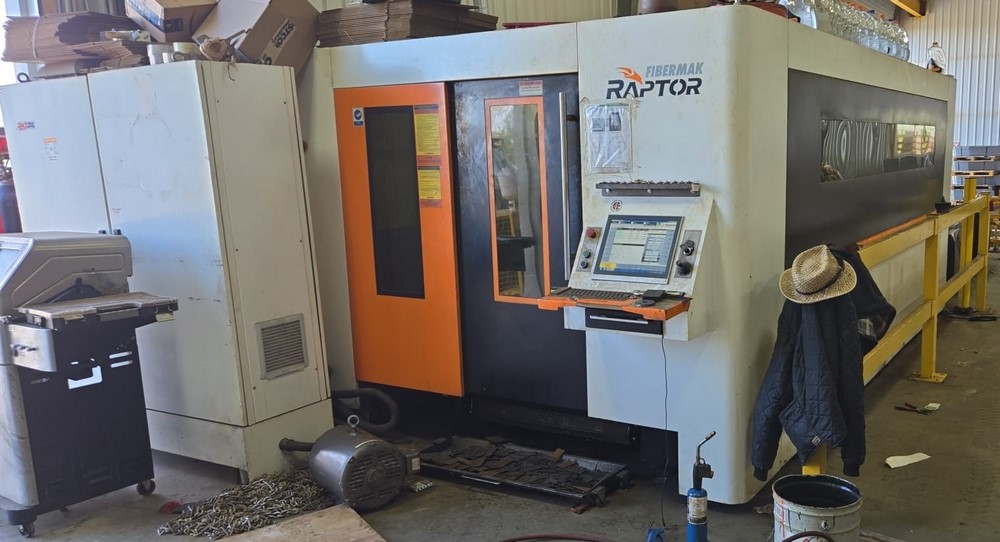
From Factory Floor to Your Workshop: Evaluating a Pre-Owned , Used , Secondhand, Surplus CNC Machines Before Purchase Ermaksan Raptor CNC Fiber Laser made in Türkiye
Here is a comprehensive “Factory Floor → Your Workshop” style evaluation guide for a pre-owned / surplus Ermaksan Raptor (Fibermak Raptor) CNC fiber laser (made in Türkiye). Use this to methodically assess mechanical, optical, control, and operational features—and to spot hidden defects before committing to purchase.
I’ll also include known specs / performance ranges for the Raptor / Fibermak laser line so you have reference benchmarks.
1. Background & Reference Specs (What to Expect)
Before inspection, familiarize yourself with what the Raptor / Fibermak series offers. This gives you baseline expectations and red-flag thresholds to challenge the seller’s claims.
From Ermaksan’s product pages and listings:
| Feature | Typical / Published Value | Notes / Sources |
|---|---|---|
| Acceleration | 1.5 G | The Raptor series is advertised at 1.5 G acceleration. |
| Maximum Cutting Speed | ~ 80 m/min | Stated performance metric for Raptor. |
| Power Options | Up to ~ 6 kW | Power class of the Raptor series includes 2.5–6 kW options. |
| Positioning Accuracy | ± 0.1 mm | The listing mentions ±0.1 mm for positioning. |
| Stroke / Travel / Working Area | e.g. 1,525 × 3,048 mm sheet sizes | The Raptor listing shows sheet W = 1,524 mm, L = 3,048 mm. |
| Axis Count / Motion | X, Y, U, Z servo axes; auto-focus head | The Raptor is described with axes X, U, Y, Z and auto-focus cutting head. |
| Controller / Software | Beckhoff controller, Metalix CAD/CAM, optional Lantek | Standard control is Beckhoff; software options include Metalix, Lantek. |
| Structure / Body | Lightweight profile body, ergonomic / modular design | The marketing highlights “light profile body” and modular design. |
These are your guiding benchmarks. If a seller claims much higher speeds, power, travel, or precision, request test-cut proof, internal logs, or optical measurement reports.
2. Pre-Screening Documentation & Remote Checks
Before you go onsite, request or examine as much documentation, images, and machine history as possible. This filtering step saves time and prevents costly surprises.
Ask / Acquire:
- Nameplate / Identification Images
– Photos of mechanical nameplates (model, serial, year)
– Electrical / control cabinet plates (voltage, phase, current) - Specification Sheet / Manual / Brochure
– The specific Raptor variant’s spec sheet
– Laser optics / resonator documentation, beam quality specs - Control System Details & Computer / Software
– Model / version of controller (Beckhoff or other)
– Firmware / software versions, backup of parameters / programs - Usage & Run History
– Total hours, laser-on / cutting hours vs idle
– Materials cut (stainless, carbon steel, aluminum, thickness ranges) - Service / Maintenance / Repair Records
– Resonator / source maintenance, optics replacement, alignment service
– Repairs to motion axes, guideways, drives, electronics - Accessories / Spares / Consumables
– Cutting head (auto-focus or standard), optics, nozzles, spare lenses, beam delivery path
– Spare control modules, servo drives, sensors - Photos / Videos in Operation
– Machine moving axes, cutting motion, beam on workpiece, marking emissions
– Close-up of optics path, beam alignment, mirror mounts, protective covers - Reason for Sale & Known Issues
– Is it replaced, idle, failing, or relocated?
– Any known defects (beam instability, alignment drift, control quirks) - Shop / Environmental Conditions
– Was the environment clean / controlled, lots of dust / smoke, temperature swings
– Maintenance habits, coolant / ventilation, cleanliness - Installation / Logistics Data
– Machine weight, footprint, power requirement, cooling (chiller), ventilation, exhaust
– Foundation / leveling needs
If the seller hides or cannot provide many of these, you should approach the machine with caution.
3. On-Site Structural & Optical Inspection
Once onsite, you must systematically inspect the mechanical, optical, and motion components.
3.1 Structure & Mechanical Integrity
- Inspect the machine frame, base, gantry or bridge for cracks, weld repairs, distortions.
- Check guideways, linear rails, ball screws or linear motors for pitting, corrosion, wear, scoring.
- Examine covers, bellows, protection for axes, whether they are intact, aligned, protective.
- Inspect beam delivery path covers, mirrors housings, beam path protection to see if there have been damage or dust ingress.
- Check cable routing, conduit, sensor housings, junction boxes for signs of wiring damage, repairs, thermal damages.
3.2 Optics & Beam Path Components
- Inspect input fiber / resonator coupling, fiber connectors, collimators for signs of contamination or damage.
- Examine mirror mounts, protective windows, lens assemblies, apertures for scratches, contamination, or misalignment.
- Check auto-focus head mechanics, focusing lens travel, lens adjustment mechanisms.
- Inspect protective glass in cutting head, nozzle alignment, lens condition.
- Look for signs of coating damage, stray reflections, blackening, soot / particulate accumulation in beam path.
3.3 Motion / Axis Kinematic Check
- Jog axes (X, Y, U, Z) slowly; feel for binding, smoothness, unsteady segments.
- Use a dial indicator or test probe to detect backlash / lost motion in axes, especially in beam head focusing travel (Z) or U-axis offsets.
- Reverse direction at endpoints to search hysteresis or deadband.
- Observe small incremental movements to ensure motion consistency (no stuttering or jumps).
- Check synchronization (if gantry or dual-axis) for squareness and parallel error.
4. Laser / Beam & Cutting Tests
If operation is permitted, run laser-beam tests to verify cutting performance.
- Fire the laser in a safe test cut (thin sheet, known material) and inspect cut quality (edge smoothness, dross, kerf uniformity).
- Test piercing behavior (hole start, delay, stability) across thickness ranges.
- Check beam stability (continuous power, no fluctuations, no power dips).
- After doing a cut, re-check alignment and reference points to detect drift.
- Test the auto-focus mechanism, whether it keeps consistent focal distance across the bed.
- If there is a marking or engraving mode, test marking performance and clarity.
- Run a longer cut / nested pattern to stress motion, thermal drift, accuracy over area.
5. Control, Electrical & Software Checks
- Open control cabinet: inspect wiring, drives, fuses, controllers, terminal blocks, connectors for damage, heat marks.
- Check servo drives, motor controllers, feedback encoders / resolvers for corrosion or damage.
- Power up: test control interface, joystick or handwheel, emergency stops, interlocks.
- Load control program / parameters: verify control memory, program backups, offsets, beam power settings.
- Inspect alarm / error logs to see past faults behavior.
- Run motion commands, test homing, offset, slow moves, acceleration profiles.
- If the control supports diagnostics (beam diagnostics, feedback), examine those readings.
6. Accuracy, Metrology & Drift Verification
- Use precision test pieces or gauge patterns to verify dimensional accuracy (hole spacing, cut-to-size).
- Check repeatability: cut same geometry multiple times, exit, re-cut, and measure difference.
- Measure cut edges for straightness, squareness, parallelism.
- After extended operation, remeasure to detect drift in beam alignment, positional accuracy.
- Check the uniformity of focus across bed: place test at different zones, see whether cut quality / kerf changes.
7. Infrastructure / Facilities & Installation Factors
- Verify that your workshop can supply proper power (voltage, phase, amperage) for the laser, cooling, chiller, control.
- Ensure cooling / chiller system is present and functioning (laser source typically needs water cooling).
- Check ventilation / exhaust / fume extraction is suitable for laser smoke removal.
- Confirm foundation / floor load capacity, anchoring, leveling.
- Examine floor flatness / alignment (important to maintain beam alignment across bed).
- Assess space for safe maintenance access (optics, resonator, electronics).
- Check availability of consumables / spare optics / replacement parts for Ermaksan / Fibermak line in your region.
8. Decision Criteria, Red Flags & Negotiation Leverage
Use your collected data to decide whether to proceed, negotiate, or walk away.
Positive / Acceptable indicators:
- Machine’s motion and axes are smooth, backlash minimal, motion repeatable.
- Optics, mirrors, beam path appear intact, clean, no damage.
- Laser-cut test yields crisp cuts, stable beam, good edge quality across full bed.
- Auto-focus works reliably and consistently.
- Control system is healthy, no error logs of chronic issues, backups exist.
- Temperature / drift behavior minimal across test cuts.
- Spare optics, parts, documentation included or readily available.
- Infrastructure (power, cooling, ventilation) aligns with machine requirements.
Red flags / deal-breakers:
- Optics damage (scratched mirrors, misaligned lens, contaminated beam path)
- Motion inconsistencies, binding zones, high backlash
- Laser beam instability, power fluctuations, erratic performance
- Poor or uneven edge quality, dross, kerf anomalies
- Auto-focus failures or inconsistent focusing
- Faulty or error-prone control electronics (burned boards, corrupt logs)
- Drift in alignment over short runtime
- Missing critical spare parts or optics that are proprietary or rare
- Impending costs to rebuild resonator / optics path
- Seller refuses cuts, optics inspection, or testing
Use any deficiencies you locate as negotiation leverage — request discounts, spare parts, guarantee, or refurbishment agreement.