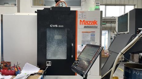
Avoid Costly Mistakes: Professional Tips for Purchasing a Pre-Owned / Second-Hand / used MAZAK CV5-500 CNC 5-Axes Vertical Machining Center made in Japan
When evaluating a pre-owned / used Mazak CV5-500 (or variant) 5-axis vertical machining center, you must perform a very careful, multi-discipline inspection. Because it’s a 5-axis machine with trunnion table, cam/gear drives, high dynamics, and tight tolerances, small defects or misalignments that might be tolerable in 3-axis machines can become fatal liabilities. Below is a professional checklist, tips, and red flags to help you avoid costly mistakes.
I’ll begin with relevant benchmark specs for the CV5-series (so you know “what good looks like”) and then the inspection and negotiation approach.
Mazak CV5-500: Benchmark & Expected Features
Before inspection, knowing the typical specs helps you detect mis-claims or exaggerations:
From Mazak’s product pages and datasheets:
- The CV5 line is framed as a next-generation simultaneous 5-axis vertical machining centre.
- For the CV5-500 variant:
• Table size: Φ 500 mm (circular table)
• Max workpiece: Φ 500 mm × 320 mm height
• Tool shank: CAT / BT 40 standard
• Standard spindle speed: 12,000 rpm
• Some versions advertise optional high-speed spindle (e.g. 18,000 rpm)
• Traverses: listings cite X = 730 mm, Y = 450 mm, Z = 470 mm
• 30-position tool magazine, fast tool-to-tool change, high reliability, trunnion table with full support on both ends (rigid support)
• Use of cam/rolling motion in B/C axes to minimize backlash, increase torque, and maintain precision in rotation axes
• Compact footprint, side-loading door, good access for maintenance
Knowing these, if a used machine claims a much higher spindle rpm, a larger table, or dramatically different travels, you must demand proof or treat with caution.
Inspection & Evaluation Checklist
Here’s a structured, in-depth checklist to apply when evaluating a used CV5-500. Take photos, videos, and instrument readings when possible, and bring test parts & tools to validate performance.
1. Pre-visit / Documentation & Screening
Before you even go on site (if possible):
- Ask for serial number, build year, and machine variant.
- Request mechanical, electrical, hydraulic, control manuals, wiring diagrams, parts lists, past calibration or alignment reports, maintenance logs, spindle rebuild history.
- Ask for videos or live remote demos showing all axes (X, Y, Z, B, C) moving, tool changes, spindle running, 5-axis interpolation moves.
- Ask seller for last few years of usage history: how many hours, how many cutting hours vs idle, what part types, whether there were crashes.
- Ask for control software backups, parameter files, custom macros, compensation tables, and whether control licenses / dongles are included.
- Check whether spare parts (especially for the cam drives, B/C axes, rotary bearings, spindle) are still available in your region.
- Confirm transport logistics: footprint, weight, lifting points, access, disassembly needs.
If the seller cannot provide sufficient documentation or refuses to show a motion demo, begin with suspicion.
2. Structural & Mechanical Condition
This is critical: mechanical issues are the hardest and costliest to fix.
a) Frame, casting, structure
- Visually inspect for cracks, weld repairs, signs of distortion or damage in the base, columns, gantry, structural members.
- Use long straightedges, precision levels, or optical methods to test reference faces (table mounting surfaces, column faces) for twist, bending, or warping.
- Check symmetry of wear—the two ends of the trunnion table or column should show similar wear, not one side much worse.
- Inspect mating faces, rails, and supports for corrosion, pitting, or gouges.
b) Guideways / rails / linear motion systems
- Move each linear axis (X, Y, Z) slowly across full travel (if allowed) and feel for stick/slip zones, rough patches, binding, jumps.
- Inspect the guide surface (linear rails, roller guides) or whatever profile the CV5 uses for signs of wear, corrosion, flaking, scoring, edge rounding.
- Check the wipers, scrapers, protective covers (bellows, shields) — missing or damaged covers let chips and coolant ruin guide surfaces.
- Inspect any preload, adjustment screws, or alignment screws/gibs for wear, looseness, or difficulty in adjustment.
c) Ball screws / feed screws / backlash
- Reverse a small movement in each axis and measure backlash / play with a dial indicator (or better instrument). For a machine of this class, acceptable backlash is tight (a few microns or less).
- Feel for nonuniform friction along the travel—zones where motion becomes harder or softer indicate local wear or damage.
- Check coupling joints between motors and screws for alignment, looseness, or wear.
- Inspect nut housings and bearing supports for play or looseness.
d) Spindle, bearings & spindle head
- Mount a precision test bar or spindle gauge and measure radial & axial runout. Even small deviations are critical in high-precision 5-axis work.
- Run the spindle (no load) over its speed range and listen/feel for bearing hum, vibration, buzzing, or abnormal sounds.
- After some run time, measure spindle housing temperature—hot spots or uneven heating are red flags.
- Inspect the spindle nose, taper, drawbar or retention mechanism, keying, and interface surfaces.
- Ask for or look for evidence of spindle rebuilds, bearing replacements, or shock events.
e) Rotary B / C axes, trunnion mechanism & cam drives
- Because the CV5 uses cam/gear rolling motion for B & C axes, test the motion of B and C—tilt the table and rotate the table. Feel for backlash, jerkiness, dead zones, or hesitation.
- Measure repeatability and backlash in the B and C axes (e.g. commanding small tilts + return).
- Check the cam / gear surfaces, roller bearings, lubrication points, wear patterns, and absence of diners or play in the gear interfaces.
- Inspect seals, lubrication lines, and bearings in the rotary axes for leaks, smoothness, or looseness.
f) Tool magazine / tool changer / ATC
- Cycle the ATC many times to test indexing speed, reliability, mis-index occurrences, and jitter.
- Inspect magazine rails, pockets, slides, sensors, actuators for wear or looseness.
- Test tool mounting repeatability—does the tool return to same position after change?
- Inspect blow-off, air purge, lubrication, and magazine cleaning systems.
g) Coolant, lubrication, support systems
- Check coolant pumps, piping, filters, sump, residue, sludge, leaks or clogging.
- Inspect lubrication circuits (oil / grease), ensure that all axes/slides are being fed. Blocked or missing lubrication is a major cause of premature wear.
- If there are hydraulic or pneumatic systems (for axis lock, lubrication, tool clamp), test for leaks, pressure stability, actuation smoothness.
- Check hoses, couplings, seals for signs of wear, brittleness, repair.
- Examine chip conveyors, guards, flushing nozzles, and chip paths for functionality and condition.
3. Electrical & Control Systems
A fully functional control system is as critical as the mechanical side.
- Power the machine up gradually (ideally under a step-up transformer or monitored supply) and watch for burning smells, abnormal voltages, tripped circuits.
- Open the electrical cabinet (if allowed) and inspect all wiring: look for brittle insulation, cracked or discolored wires, splices, amateur repairs, overheating marks.
- Boot the CNC control system: check the UI, display, diagnostic screens, memory, error logs.
- Jog each axis in manual/MDA mode, at various speeds. Observe smoothness, stutters, reversals, direction changes.
- Test multi-axis coordinated moves (e.g. X + Y + Z + B + C) to see how well the machine interpolates and how smoothly the axes synchronize.
- Check encoder or feedback systems (absolute, incremental, linear scales, resolvers), confirm consistent signals with no glitches or noise.
- Test homing routines, limit switches, overtravel protection, interlock circuits, emergency stops.
- Ensure all software parameter sets, backup files, macros, license keys, compensation tables are included and functional.
- For older custom or proprietary control modules, verify whether spare boards or repair support is still available.
If the control system is obsolete or unserviceable (no spares, no support), the machine’s value significantly decreases.
4. Functional / Cutting Test & Acceptance Trials
Testing under load is nonnegotiable — idle movements don’t reveal true performance.
- Bring a representative workpiece and tools (e.g. difficult geometry, 5-axis moves) and run a full machining cycle.
- Execute complex simultaneous 5-axis interpolated moves, including tilt + rotation + linear axes together.
- Monitor for stalling, vibration, axis synchronization errors, Cartesian deviations.
- Perform return-to-zero / repeatability tests (move away & return in multiple axes) and measure deviation with high-precision instrumentation.
- After cutting, measure critical features: flatness, positional accuracy, angular errors, surface finish, tool path consistency.
- Run extended cycles (hours) to observe thermal drift / alignment shift as the machine warms.
- Test repeated tool changes mid-program, measure resumption accuracy.
- Test all auxiliary systems (coolant, chip evacuation, guards, magazine, motion under coolant) under working conditions.
- If available, run stress/edge cases (high feed rates, heavy side milling) to provoke weaknesses.
If the seller refuses to let you run cutting tests or limits you to idle jogging, that is a glaring red flag.
5. Geometry & Alignment Verification
Given the multi-axis, trunnion structure, geometry is everything in 5-axis machining.
- Request any past alignment, laser calibration or ballbar reports.
- Use your own metrology tools (or hire a specialist) to check:
* Squareness between linear axes
* Straightness of travel in X, Y, Z
* Angular error of spindle relative to axes
* Tilt / angular accuracy of B, C axes (tilt homing repeatability)
* Backlash / hysteresis in all axes
* Surface flatness / parallelism of table to axes - Check whether the control supports geometric compensation, error mapping, or correction tables, and whether they are correctly configured.
- If misalignment is significant, assess whether re-alignment (shim work, straightening, re-leveling) is feasible and economical.
6. Spare Parts, Service & Support
One of the biggest “hidden costs” in used 5-axis machines is the inability to acquire spares or get support.
- Verify availability of critical spares: spindle bearings, cam gears, rotary axis bearings, drive modules, control boards, encoder systems, ATC parts.
- Check whether Mazak (or regional Mazak support) still services CV5-series or its components in your region.
- Ask about aftermarket / third-party support for 5-axis components (gear replacements, cam refurbishing).
- Evaluate whether retrofitting a newer control (if the current one becomes obsolete) is structurally feasible.
- Confirm that tooling and accessories (holders, cutters, fixtures for 5-axis) for the machine’s interface are still obtainable.
- Try to get spare modules (e.g. backup electronics boards) or wear items (seals, bearings) as part of the deal.
If spare parts or repair support are scarce or prohibitively expensive, that weakens the machine’s long-term value.
7. Contractual Safeguards & Negotiation Leverage
You must protect yourself in writing — many issues manifest after delivery or after burn-in.
- Insist on conditional acceptance / acceptance testing: full payment only once the machine passes your test program.
- Define quantitative acceptance criteria: maximum allowed runout, repeatability tolerances, angular errors, surface finish limits, backlash thresholds.
- Request a short warranty / guarantee period (e.g. 30–90 days) covering critical systems (spindle, B/C axes drives, control).
- Ensure that all documentation (manuals, wiring, software, alignment records) be delivered.
- Clarify responsibility for transport, rigging, leveling, foundation preparation, site modifications, commissioning, alignment, and re-grouting.
- Include a “burn-in / commissioning period” clause, so defects discovered under real usage must be remediated by the seller.
- Insist on written disclosures of any known defects, repairs, structural modifications, or past crashes.
8. Transport, Installation & Commissioning
Even a perfect machine is vulnerable during move and setup.
- Confirm accurate machine weight, footprint, center-of-gravity, and whether partial disassembly is required.
- Use proper rigging, supports, shock absorption, and securement to avoid stress or distortion during transport.
- After installation, re-level, anchor or re-grout, ensuring foundation rigidity and damping.
- Allow a commissioning / burn-in period before declaring the machine accepted.
- Once stabilized, repeat alignment tests to catch any shift in installation.
- Be present (or send your technical staff) for initial production runs to monitor performance, verify tolerances, and catch problems early.
9. Red Flags & Deal-Breakers
Be very cautious (or walk away) if any of the following are present:
- Seller refuses full inspection, disallows cutting tests, or blocks internal access.
- Evidence of structural repairs, welds, or misaligned castings in base, columns, or trunnion.
- Spindle with noise, excessive runout, overheating, missing rebuild history.
- Lack of smooth operation or backlash in cam/gear drives (B / C axes).
- Linear axes showing zones of binding, roughness, or wear.
- Control or electronics are obsolete, proprietary, or lack spare parts.
- Wiring harnesses, insulation, connectors are cracked, brittle, heavily spliced, or show burn/repair traces.
- Missing or incomplete documentation (manuals, wiring, software backups, alignment records).
- ATC / tool magazine mis-indexes, jams, or is unreliably slow.
- Coolant, lubrication, hydraulic systems in poor condition (leaks, blockage, contamination).
- Spare parts for critical systems (spindle bearings, cam drives, electronics) are unavailable or hard to source.
- Excessive wear in guides, screws, rotary axes, making refurbishment cost nearly as much as replacement.
- Hidden damage from floods, coolant corrosion, neglect, or collision damage.