What is Pantograph Machine?
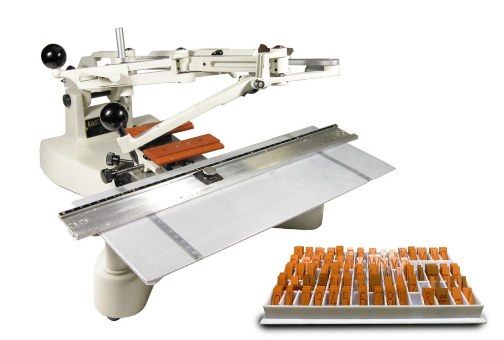
A pantograph machine is a mechanical linkage device based on a parallelogram structure, historically used for copying, scaling, and reproducing drawings or engravings with precision. It operates by translating the motion of a stylus or tracer point to a pen or tool, either replicating the original design at the same scale or producing a scaled-up or scaled-down version. Below is a technical explanation of its design, operation, and applications:Technical Description
- Structure and Components:
- A pantograph consists of a series of interconnected bars forming a parallelogram linkage, typically arranged in a rhombus or diamond shape.
- Key components include:
- Pivot points: Joints that allow the bars to rotate relative to one another.
- Tracer point/stylus: A point that traces the original drawing or template.
- Drawing tool/pen: The output point that replicates or scales the traced design.
- Fulcrum: A fixed pivot point that anchors the pantograph to a surface.
- The bars are connected such that the tracer and pen move in a geometrically similar path, maintaining proportional motion.
- Working Principle:
- The pantograph operates on the principle of geometric similarity. The linkage ensures that the motion of the tracer point is mirrored by the drawing tool, with the scale determined by the ratio of the lengths of the pantograph’s arms.
- Mathematically, the scaling factor ( k ) is determined by the ratio of the distances between pivot points. For example, if the distance from the fulcrum to the tracer is L1L_1
L_1and to the pen is L2L_2L_2, the scaling factor is k=L2/L1k = L_2 / L_1k = L_2 / L_1. - The parallelogram structure ensures that angles and shapes are preserved, allowing accurate reproduction of complex curves and patterns.
- Scaling Mechanism:
- To scale a drawing, the pantograph is adjusted by setting the pivot points or arm lengths. For instance:
- If L2>L1L_2 > L_1
L_2 > L_1, the output is an enlarged version of the input. - If L2<L1L_2 < L_1
L_2 < L_1, the output is a reduced version.
- If L2>L1L_2 > L_1
- The scaling is uniform in both the x and y directions, preserving the aspect ratio of the original design.
- To scale a drawing, the pantograph is adjusted by setting the pivot points or arm lengths. For instance:
- Operation:
- The user moves the tracer point over the original drawing or template.
- The linkage translates this motion to the drawing tool, which moves synchronously to produce the scaled copy on a separate surface.
- The pantograph is typically mounted on a stable surface to ensure precision and minimize errors due to vibrations or misalignment.
Mathematical BasisThe motion of the pantograph can be described using coordinate geometry:
- Let the tracer point be at position (xt,yt)(x_t, y_t)
(x_t, y_t)relative to the fulcrum. - The drawing tool’s position (xp,yp)(x_p, y_p)
(x_p, y_p)is related by the scaling factor ( k ):xp=k⋅xt,yp=k⋅ytx_p = k \cdot x_t, \quad y_p = k \cdot y_tx_p = k \cdot x_t, \quad y_p = k \cdot y_t - The parallelogram linkage ensures that the relative angles and distances are maintained, so the output is a homothetic transformation (a scaled replica) of the input.
Technical Specifications
- Materials: Pantographs are typically made from rigid materials like steel, aluminum, or wood to ensure stability and minimize flexing.
- Precision: High-quality pantographs achieve accuracies within fractions of a millimeter, depending on the craftsmanship and materials.
- Degrees of Freedom: The device operates in two dimensions (x-y plane), with the tracer and pen constrained to move in parallel planes.
Applications
- Historical Uses:
- Drafting and Cartography: Used in the 17th–20th centuries to copy and scale technical drawings, maps, and engravings.
- Engraving: Employed to transfer designs onto metal plates for printing or coin minting.
- Modern Uses:
- CNC Machining: Modern pantograph-inspired mechanisms are used in CNC routers and engraving machines for precise scaling and replication.
- Art and Design: Artists use pantographs for scaling sketches or creating large murals from small drafts.
- Industrial Applications: Used in manufacturing for duplicating patterns or templates onto workpieces.
- Electrical Engineering:
- In railway systems, a pantograph refers to a different device—a spring-loaded mechanism on electric trains that collects power from overhead lines. This is unrelated to the mechanical drafting pantograph but shares the name due to its similar articulated structure.
Advantages
- Simple, purely mechanical design requiring no power source (for traditional pantographs).
- High precision for replicating complex shapes.
- Adjustable scaling for versatile applications.
Limitations
- Limited to 2D replication; cannot handle 3D objects directly.
- Manual operation can be time-consuming for large or intricate designs.
- Modern digital tools (e.g., CAD software, laser cutters) have largely replaced traditional pantographs in many applications.
Historical Context
- Invented by Christoph Scheiner in 1603, the pantograph was a revolutionary tool for artists, engineers, and cartographers.
- It was widely used until the advent of digital reproduction technologies in the late 20th century.
In summary, a pantograph machine is a mechanical device that leverages a parallelogram linkage to replicate or scale drawings with high precision. Its technical elegance lies in its simplicity and geometric accuracy, making it a historically significant tool in drafting and engineering, though its role has diminished with modern technology.