| GENERAL CAPACITY |
| Models |
SL-8 / SL-8B / SL-8A / SL-8C / SL-8F |
SL-8 / SL-8B / SL-8A / SL-8C / SL-8F |
| Swing Over Bed – SL-8 / SL-8B / SL-8A / SL-8C |
Ø1,000 mm |
Ø39.3 in |
| Swing Over Bed – SL-8F |
Ø1,300 mm |
Ø51.1 in |
| Swing Over Carriage – SL-8 / SL-8B / SL-8A / SL-8C |
Ø900 mm |
Ø35.4 in |
| Swing Over Carriage – SL-8F |
Ø1,100 mm |
Ø43.3 in |
| Maximum Machining Diameter – SL-8 |
Ø600 mm |
Ø23.6 in |
| Maximum Machining Diameter – SL-8B |
Ø900 mm |
Ø35.4 in |
| Maximum Machining Diameter – SL-8A / SL-8C |
Ø600 mm |
Ø23.6 in |
| Maximum Machining Diameter – SL-8F |
Ø1,300 mm |
Ø51.1 in |
| Maximum Longitudinal Travel |
1,100 mm |
43.3 in |
| Maximum Cross Travel |
420 mm |
16.5 in |
| SPINDLE CENTER HEIGHT |
| Spindle Center Height from Floor – SL-8 |
1,250 mm |
49.2 in |
| Spindle Center Height from Floor – SL-8B |
1,390 mm |
54.7 in |
| Spindle Center Height from Floor – SL-8A |
1,250 mm |
49.2 in |
| Spindle Center Height from Floor – SL-8C |
1,390 mm |
54.7 in |
| Spindle Center Height from Floor – SL-8F |
1,630 mm |
64.1 in |
| SPINDLE |
| Programmable Spindle Speed – SL-8 |
4 – 550 RPM |
4 – 550 RPM |
| Programmable Spindle Speed – SL-8B |
4 – 550 RPM |
4 – 550 RPM |
| Programmable Spindle Speed – SL-8A |
5 – 750 RPM |
5 – 750 RPM |
| Programmable Spindle Speed – SL-8C |
6 – 370 RPM |
6 – 370 RPM |
| Programmable Spindle Speed – SL-8F |
High: 2.5 – 143 RPM
Medium: 1.5 – 85 RPM
Low: 1 – 57 RPM |
| Spindle Nose – SL-8 / SL-8B |
A1-20 |
A1-20 |
| Spindle Nose – SL-8A |
A2-15 |
A2-15 |
| Spindle Nose – SL-8C |
A2-20 |
A2-20 |
| Spindle Nose – SL-8F |
A2-15 |
A2-15 |
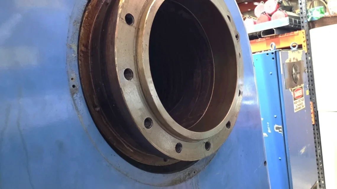
| Spindle Bore – SL-8 / SL-8B |
Ø260 mm |
Ø10.2 in |
| Spindle Bore – SL-8A |
Ø216 mm |
Ø8.5 in |
| Spindle Bore – SL-8C |
Ø370 mm |
Ø14.5 in |
| Spindle Bore – SL-8F |
Ø216 mm |
Ø8.5 in |
| Spindle Inside Taper – SL-8 / SL-8B |
Ø268 mm / 1:20 Taper |
Ø10.55 in / 1:20 Taper |
| Spindle Inside Taper – SL-8A |
Ø224 mm / 1:20 Taper |
Ø8.82 in / 1:20 Taper |
| Spindle Inside Taper – SL-8C |
Ø274 mm / 1:20 Taper |
Ø10.79 in / 1:20 Taper |
| Spindle Inside Taper – SL-8F |
Ø224 mm / 1:20 Taper |
Ø8.82 in / 1:20 Taper |
| BED, CARRIAGE & TURRET |
| Bed Width |
700 mm |
27.5 in |
| Overall Carriage Width |
700 mm |
27.5 in |
| Carriage / Bed Slant |
60° / 60° |
60° / 60° |
| Turret Tool Positions |
6 Tools |
6 Tools |
| Standard Cutting Tool Size |
Ø32 mm |
Ø1.26 in |
| Curvic Coupling Diameter |
Ø420 mm |
Ø16.5 in |
| MOTOR & MACHINE WEIGHT |
| Main Motor – SL-8 / SL-8B / SL-8A / SL-8C |
DC 45 kW |
60 HP |
| Main Motor – SL-8F |
DC 37 kW |
50 HP |
| Machine Weight – SL-8 / SL-8B / SL-8A / SL-8C |
16,000 kg |
35,200 lb |
| Machine Weight – SL-8F |
17,000 kg |
37,400 lb |
| STANDARD ACCESSORIES |
| Chip Conveyor |
1 Set |
1 Set |
| Complete Coolant System |
1 Set |
1 Set |
| Splash Guard |
1 Set |
1 Set |
| Tool Holders |
1 Set |
1 Set |
| Hydraulic Unit |
1 Set |
1 Set |
| Hand Tools |
1 Set |
1 Set |
| OPTIONAL ACCESSORIES |
| Hydraulic Chuck Unit |
Optional |
Optional |
| 4-Jaw Independent Chuck |
Optional |
Optional |
| Extra Tool Holders |
Optional |
Optional |
| FANUC NUMERICAL CONTROL UNIT |
| Controlled Axes |
Simultaneously Controllable Axes: Two Axes (One Axis by Manual); Linear and Circular Interpolations |
| Minimum Output – X Axis |
0.005 mm |
0.0002 in |
| Minimum Output – Z Axis |
0.001 mm |
0.00004 in |
| Minimum Input |
0.01 mm or 0.001 mm |
Diameter designation applicable for X axis |
| SPINDLE FUNCTIONS |
| Spindle Speed Command |
Direct designation of RPM with S 4-digit |
| Constant Surface Speed Control |
Direct designation of surface speed with S code; G96 Control ON / G97 Control Cancel |
| Maximum RPM Setting |
Maximum RPM setting for constant surface speed control; command G50 S 4-digit |
| Spindle Inching |
Spindle jog function; effective in automatic and manual modes; set at 1/100 of maximum RPM |
| FEED FUNCTIONS |
| Rapid Feed – X Axis |
5,000 mm/min |
196.9 IPM |
| Rapid Feed – Z Axis |
8,000 mm/min |
314.9 IPM |
| Synchronous Feed |
Feed per Revolution – mm/rev (G99) |
Feed per Revolution (G99) |
| Asynchronous Feed |
Feed per Minute – mm/rev (G98) |
G98 Feed Command |
| Feed Override |
0 – 200% in 10% Increments |
0 – 200% in 10% Increments |
| Dwell |
Stoppage Time Command G04 |
| Zero Return |
Machine Reference Point Return: G27, G28, G29 |
| Manual Pulse Generator |
Pulse Feed: 0.01 mm / 0.001 mm |
Pulse Feed: 0.00039 in / 0.000039 in |
| Manual Continuous Feed |
Jog Feed: Approx. 0 – 2,000 mm/min / 25 Steps |
Approx. 0 – 78.7 IPM / 25 Steps |
| Dry Run |
Manual continuous feed rate operation ignoring programmed feed command |
| TOOL FUNCTIONS |
| Tool Position Offset |
16 Pairs / 0 to ±999.999 mm |
16 Pairs / 0 to ±99.9999 in |
| Incremental Offset |
Allows a new offset value to be added to a previous offset value |
| PROGRAMMING FUNCTIONS |
| Programming System |
Absolute and Incremental |
Absolute and Incremental |
| Chamfering / Corner R |
Direct designation of chamfering amount or corner R against 90° straight cutting |
| Circular Radius R Designation |
Direct designation of circular radius R in circular interpolation instead of designating the center of a circle |
| Tool Nose Radius Compensation |
G40 Offset Cancel; G41 Left Offset; G42 Right Offset |
| Single Fixed Cycle |
G90 Cutting Cycle A; G92 Thread Cutting Cycle; G94 Cutting Cycle B |
| Multiple Repetitive Cycle |
G70 Finishing Cycle; G71 O.D. Rough Cutting Cycle; G72 Face Rough Cutting;
G73 Closed Loop Cutting Cycle; G74 Face Grooving and Deep Hole Drilling Cycle;
G75 O.D. Grooving and O.D. Cut-Off Cycle; G76 Thread Cutting Cycle |
| Decimal Point Input |
Decimal point can be used for numeric commands in tape and MDI modes |
| Block Delete |
Function to ignore blocks marked with “/” on a tape |
| Inch / Metric Conversion |
G21 Metric Input |
G20 Inch Input |
| Optional Stop |
M01 Optional Stop Function |
| THREAD CUTTING FUNCTIONS |
| Thread Cutting Lead – F Code |
0.01 – 500.00 mm/rev |
0.0001 – 50.0000 in/rev |
| E 6-Digit Thread Cutting |
0.0001 – 500.0000 mm/rev |
0.000001 – 9.999999 in/rev |
| TAPE / MEMORY FUNCTIONS |
| Tape Memory & Edit |
Memory Storage: 20 m; Deletion, Insertion, Alteration, etc. |
| Search Function |
Sequence Number Search and Other Word Search |
| Tape Punching Interface |
For FACIT 4070 |
| Buffer Register |
Advanced Tape Reading |
| CRT / Braun Tube |
Data Input Keyboard and Display Unit (CRT) |
| MISCELLANEOUS CNC FUNCTIONS |
| Machine Lock |
Machine Lock Function |
| Single Block |
Executes Commands Block by Block |
| Memory Protect |
Key Switch to Prevent Program from Being Destroyed by Improper Operation |
| Stored Stroke Limit |
Software-Controlled Over-Travel Limiting Function |